
Any sufficiently advanced technology is indistinguishable from magic.
– A. Clarke
Goals
A small flight video recorder is built for the purpose of recording an HD movie video after power up. Plug and run.
It is desirable to have a high-quality H.264 encoding with the best quality and trade-off between resolution and frame-rate (e.g. we prefer 60p and higher versus 30p for action scenes, 120FPS would also be desirable). In terms of functionality, we would like something similar to a traditional GoPro HD camera (a now insanely popular action recording camera). However, we don’t want to be plagued with pushing buttons, checking status LED’s, or interacting with a touch-screen. We really want to connect power and be recording live in 10 seconds. We would also like to have a system where the camera is as small as possible and can be remotely installed (e.g. via an umbilical cable versus a fixed mount chassis like on the GoPro).
Our other goal is to support a small, robust, rugged, and reliable flight recording package which is modern, Linux based (e.g. provides a getty/serial console as a basic form of administrative interaction), extensible and fully programmable while being adaptable to space constrained and low-power environments.
We would also like to be able to have the full power of Linux Networking and use Ethernet, Bluetooth, Wireless, Software defined Radio (ala USB+RTL-SDR), the DNT900 digital modem as found on RFS GPS-1, and other Satellite and Broadband communications systems. Most importantly, the other factor is cost – we’d like to have a sub $100 solution (without the battery).
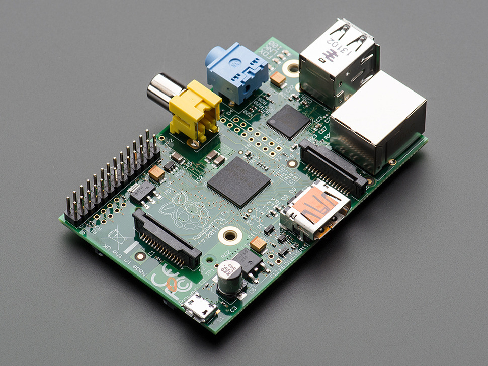
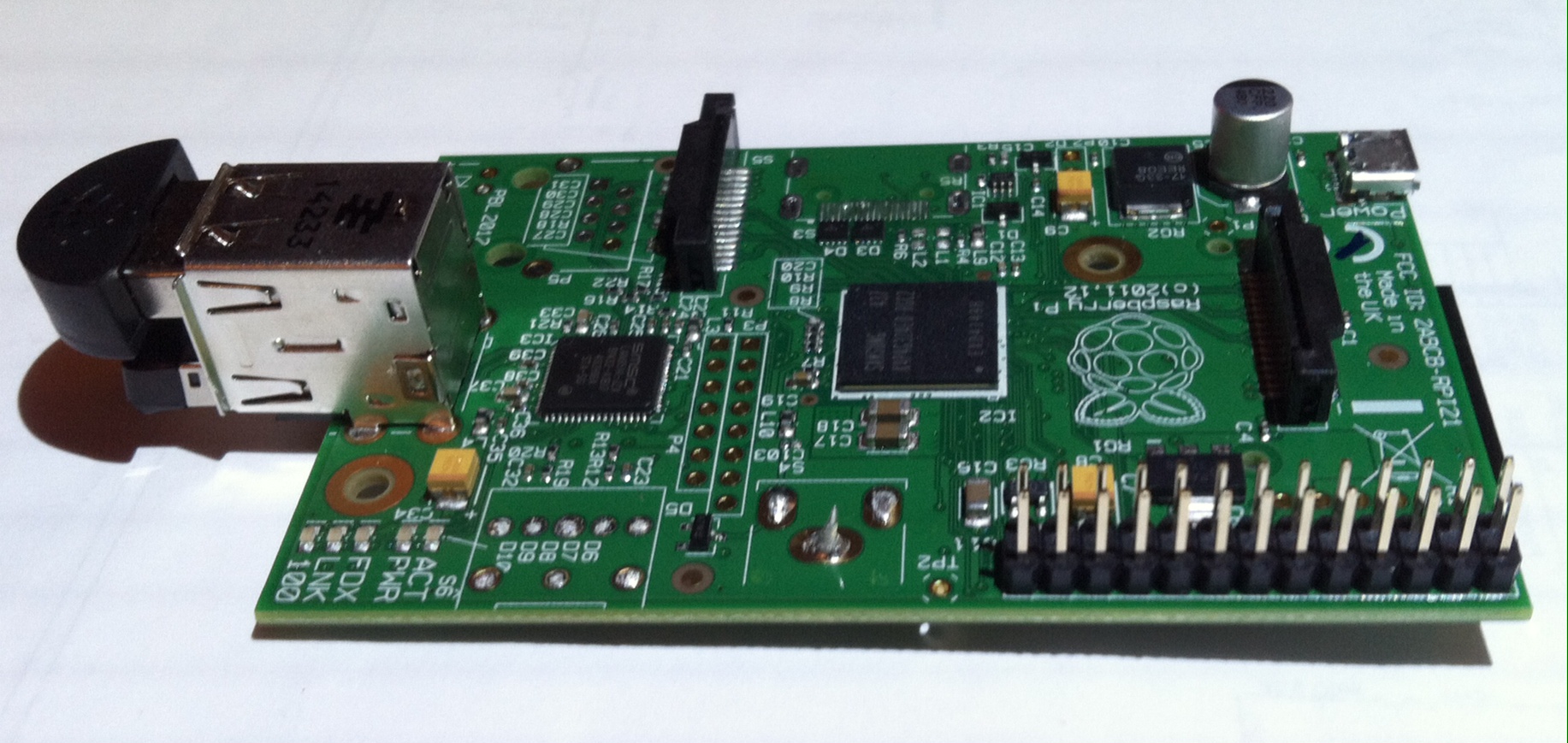
The Raspberry Pi board based on the Broadcom 2835/2836 mobile processor and the software from the Raspberry Pi foundation make all of this possible!
Hardware Components
- Raspberry Pi Model B – $39.95 or less – note, other models may be used but we chose the Model B since it has the larger 512MB of memory, and we plan to remove most all the components making a Model B+ unnecessary. Usage of the Pi-2 and derivatives will be adapted for future applications.
- Low-profile microSD card adapter for Raspberry Pi – $2.50
- Raspberry Pi Camera Board – $29.95 or less
- Universal Battery Elimination Circuit (UBEC) – $4 or less, see also http://www.ebay.com/itm/310829027973
The total price for the above is under $100. Now, we get to the expensive parts – storage and batteries:
- Enough battery to run for 2-3 hours, 7.4V Lipo with 2000+ Ma and tested in High G-Loading environments, we like the Tenergy 7.4V 2600 mAh Li-Ion Batteries (18650×2) ($19.99). It peaks at 3.3A and is a 1.5C battery. Weight 2.5 – 3oz, buy 4 at a time from Tenergy (All-Battery) for the best prices and you will get a couple light ones and a couple heavy ones (usually) (where heavy is 3oz).
- Also consider LIPO 7.4v 900/2000 mAh ($10.99) which has been also tested in High-G environments however it is not as durable.
- Micro-SD Card – we use Sandisk “Ultra” MicroSD HC Class 10 Memory card as used for Android – 32GB was chosen for best expandability ($20). This media is capable of HD 1080p recording with very little CPU load for SDIO operations. SD-Cards are leaping by great bounds – look here for more information on the best cards.
There are also some other interesting options worth considering:
- TTL / USB Cable (must have for development) ($9.95)
- Adafruit Spy Camera for Raspberry-Pi, ($39.95) for the ultimate in size. NOTE: older (circa 2013-2014 cameras do not have a RED LED indicating recording so an external GPIO and LED could be used if visual indications are required or get the new model spy camera from Adafruit (02/28/15).
Power Reduction
The primary system power requirements are:
– BCM2835/LPDDR2 memory – CPU (Linux), Video Encoder, SDIO (Micro-SD Card)
We also want to remove as many components to reduce weight and size.Normally, an R-Pi Model B with the camera module consumes power as below:
- Camera Module (Spy or regular) : ~250ma
- Pi Board (as-is) just doing encoding 720p/1080p: 400-600mA (no peripherals connected). Peaks of 1A at power-up.
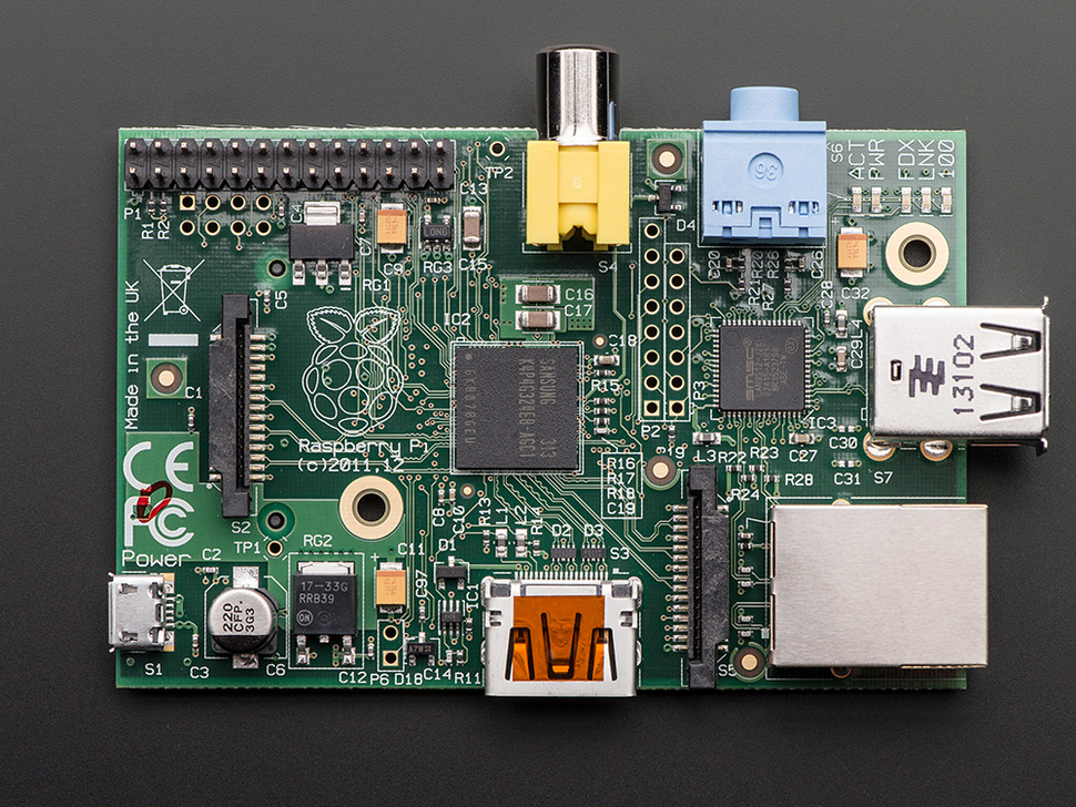
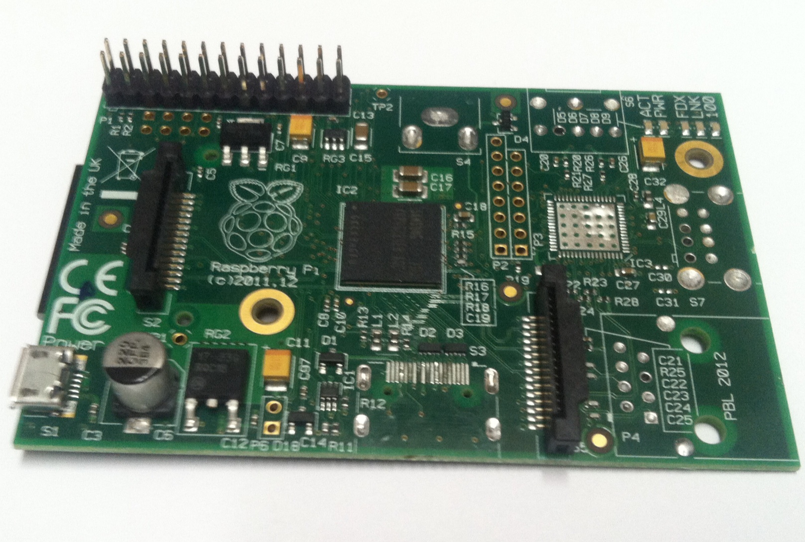
This implies we would need (worst case) roughly a 1000mAh battery for one hour of usage (assuming the relatively flat discharge curve of LiPo batteries)! Quite a waste when you consider our basic requirements. To look at power in more detail, we used an Agilent 34411A Multimeter in ammeter mode. We found the LAN9512 does consume considerable power and the connectors are also consuming space; consequently we remove the following from the R-Pi Model B:
- HDMI output port
- Composite video output
- USB port
- 3.5mm audio jack
- Microchip LAN9512 10/100 + Dual USB
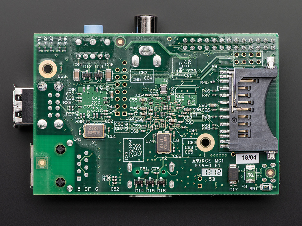
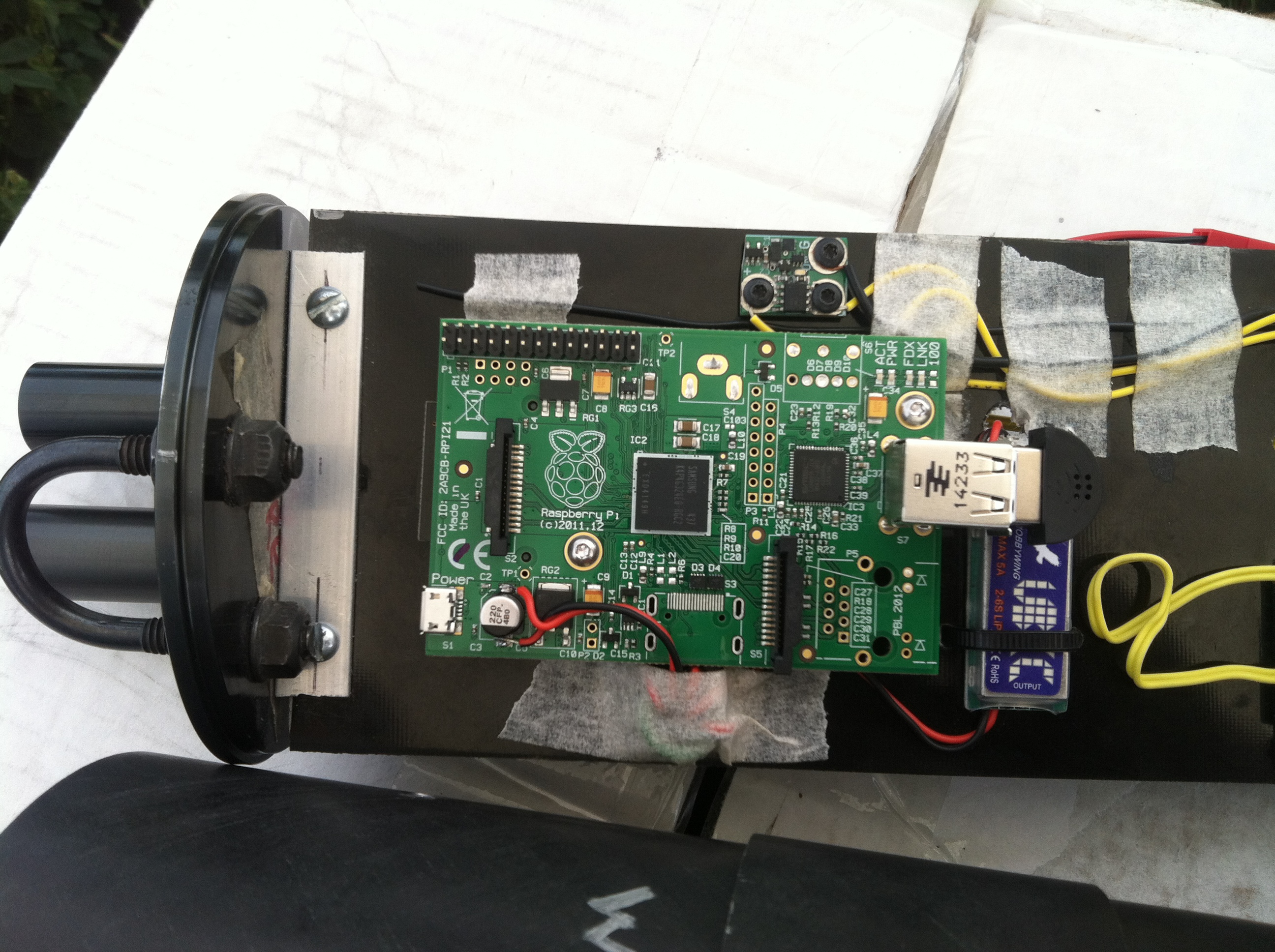
The fully de-populated board is as above. The new power-measurements are (for 5V draw only):
- 720p encoding (White Noise – worst case Encoder input): 350-350ma
- 720p encoding (Pictures, less motion): 265-300ma
We then measured the UBEC current draw using the Tenergy 2600mAh Li-Ion (18650×2) battery pack, and found the following:
- Power-up draw: up to 1100ma (over 1A)
- Normal consumption: 220mA
- Average consumption: 250mA
- White noise encoding power consumption: 260ma Peak
This implies that we should be able to run (in normal conditions) for ~10hrs with a 2600mAh battery. It also means we can save weight and shoot for a 3-hour run time with a 900mAh battery. We can go with the cheaper 2200 Ma variant of the Tenergy battery (part #31003).
In the end, the above is the basic 10hr setup with no audio but the longest record time with the 720p60 configuration for 8-10hrs. Suitable for Rockets, UAV or spy activities.
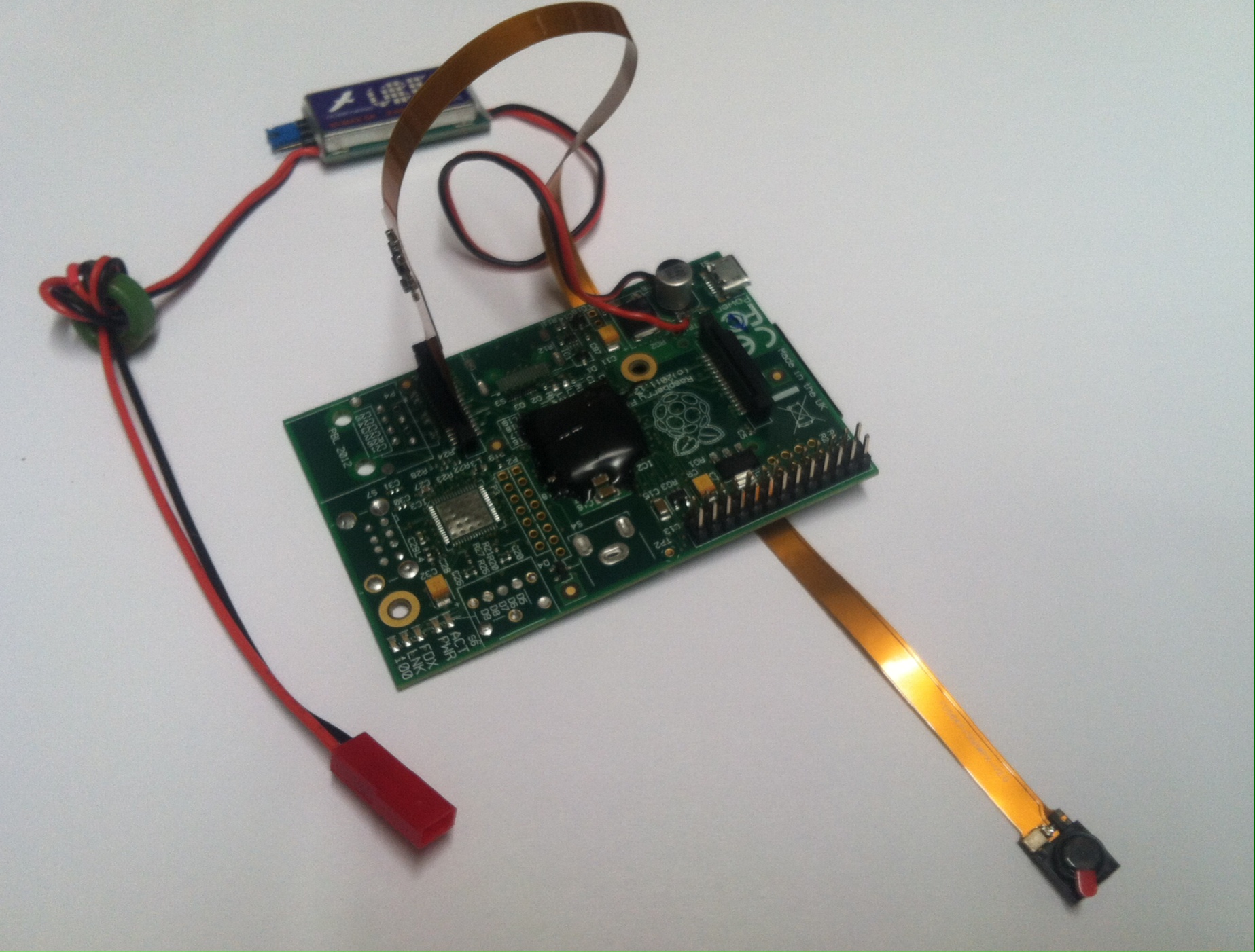
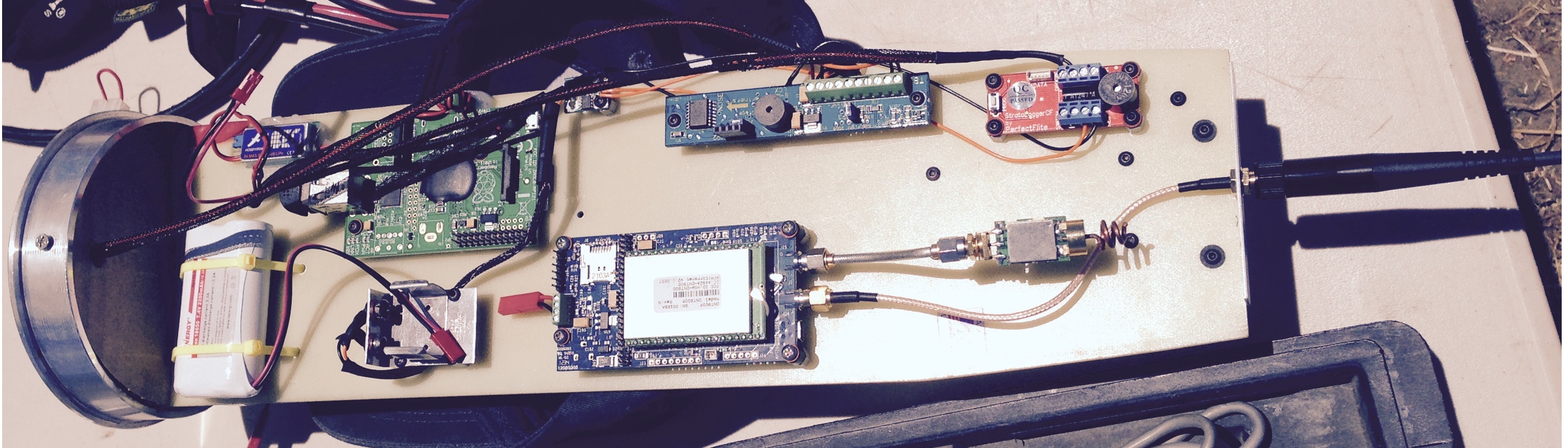
G-Protection and 5V Power Attachment
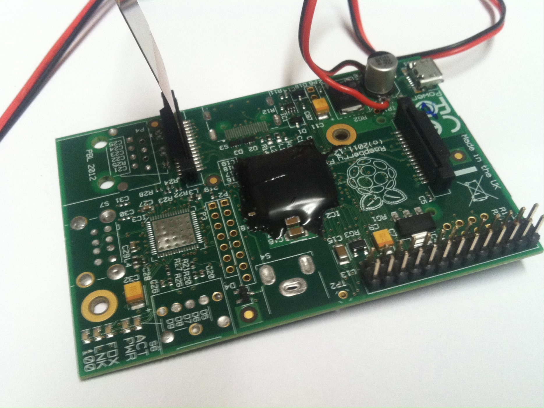
Unusual stresses in lateral and longitudinal directions may deform the PCB only momentarily yet this may be enough to depopulate (depop) the 2835 ASIC or it’s DDR2 memory. The R-Pi uses a technology called a “Pop-Top” or “sandwich” where the memory is soldered to the top of the processor and the bottom of the processor is soldered to the system board. This type of ASIC and PCB architecture is incredibly efficient and low cost, however, it may suffer from accidental depopulation of either component under G-load. To protect against accidental depopulation of the BCM2835 or LPDDR2 pop-top assembly on the Pi board, the entire BCM2835+DDR is encapsulated using Cotronics 4525 Epoxy high-temperature, electrically resistant encapsulating resin. The UBEC is carefully soldered to the pads on USB 5V power decoupling capacitor C6 (see the R-Pi schematic for details)
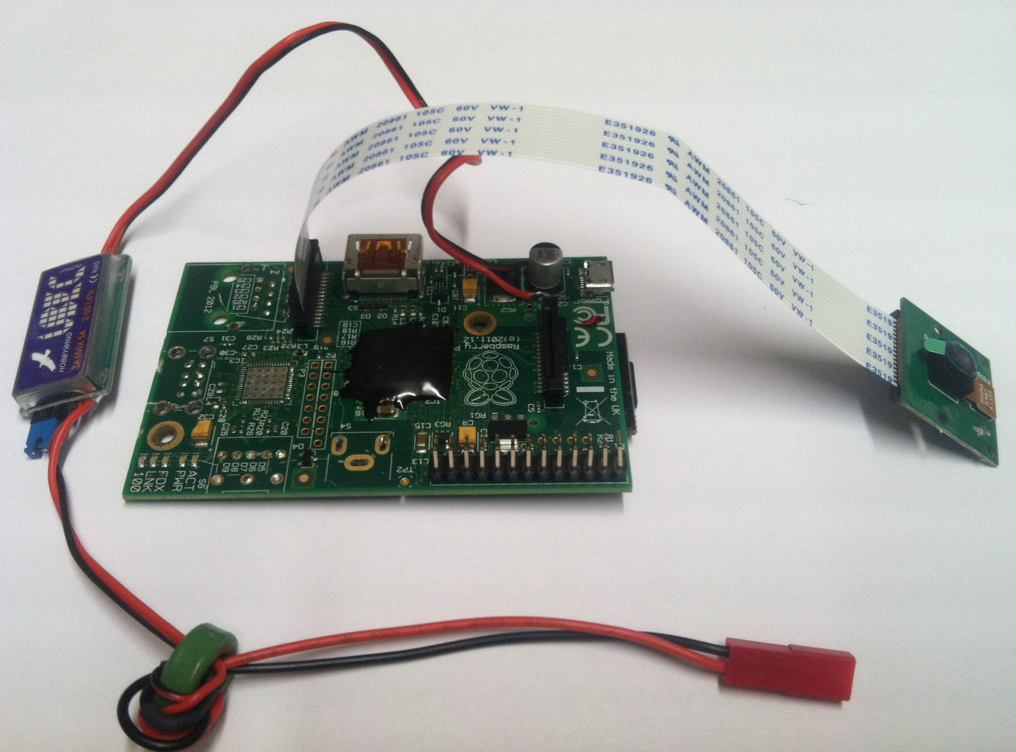
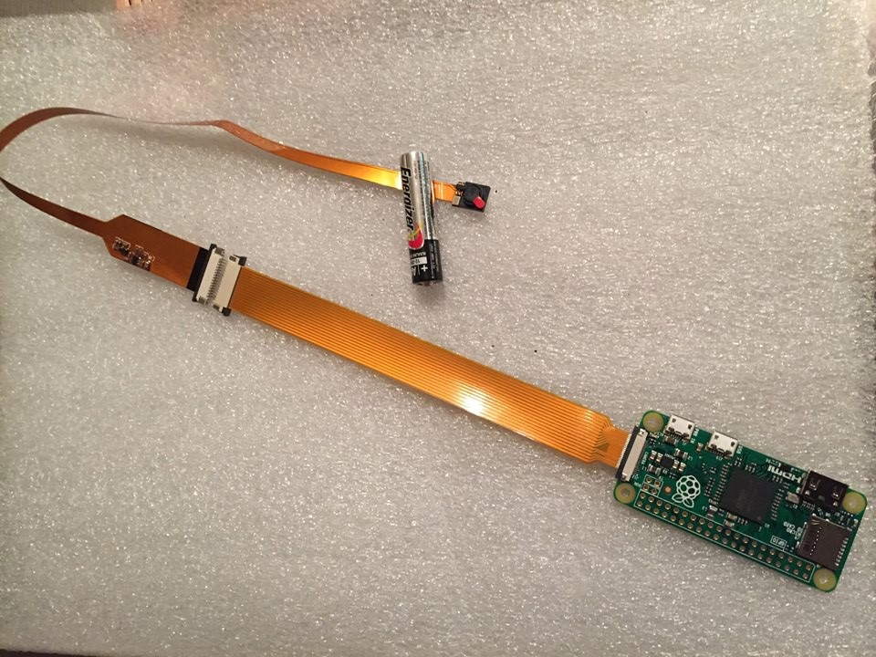
Pi Camera Connection
Both the “Spy” and the standard Pi Cameras are shown. Note that one of the boards still has an HDMI connector attached for local display viewing with the HDMI connector still attached.
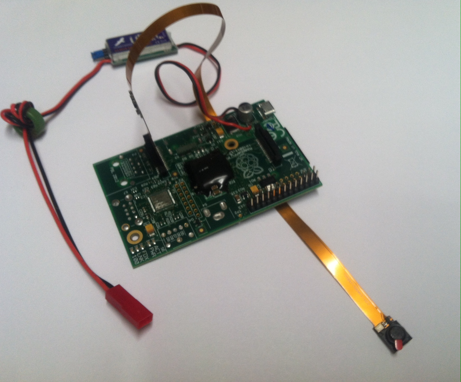
The spy camera requires a .29″ hole to be drilled and will be flush with 3/16″ thick material (19/64″ titanium drill bit recommended for the cleanest cuts through all materials – aluminum, carbon fiber, or plain G10/G12).
Serial Console
The Rasperry Pi model B/B+ GPIO is shown below for reference. The serial console is attached using the TTL Serial to USB Cable using 3-pins (null-modem style) connecting pins as follows: USB RX->Pi TX, USB TX-> Pi RX, GND->GND.
Login to Pi
When your serial console (cable) is connected, you can login to the system using username “pi”, password “pi”. The root password is also “pi” – use minicom at 115200, N,8,1 with no HW flow control to operate your terminal (getty). Stock Raspbian systems also support the sudo enabled user “rpi” with pass “rpi”. Either is fine. Use “sudo” in either account for superuser privileges.
Software
For reference, I am a Unix user. I’m an expert on either Windows or MacOS (also Unix of the BSD variant), but use Unix – Linux in most cases. For purpose of this project, I use Ubuntu 12.04 or later as my base host (development) system. This makes cross-development a snap as well. Now let’s get started. So, to begin with, Raspbian is installed on a Pi card with an SD-Card format as below:
#sudo fdisk /dev/mmcblk0

Command (m for help): p

Disk /dev/mmcblk0: 31.9 GB, 31914983424 bytes
4 heads, 16 sectors/track, 973968 cylinders, total 62333952 sectors
Units = sectors of 1 * 512 = 512 bytes
Sector size (logical/physical): 512 bytes / 512 bytes
I/O size (minimum/optimal): 512 bytes / 512 bytes
Disk identifier: 0x00000000

 Device Boot Start End Blocks Id System
/dev/mmcblk0p1 2048 411647 204800 b W95 FAT32
/dev/mmcblk0p2 411648 8800255 4194304 83 Linux
/dev/mmcblk0p3 8800256 62333951 26766848 b W95 FAT32
Command (m for help):
The disk images and installation scripts can be found here. The “scripts” directory has the installation scripts for 32GB Sandisk Ultra Media (out of the box) and the media directory has the contents of the SD-Card images ready to go. You should copy the media directory under the scripts directory (so you have a scripts/media folder) and then “gunzip all of the tar-files for the three partitions above. Now, run the top-level script “make_dish.sh” after inserting your Sandisk 32GB Ultra SD-Card. Note: I am using a Linux machine (Ubuntu 12.04 LTS).
# sudo sh make_disk.sh
Next remove your SD-Card and then re-insert it, your disk should now show up in your file-manager. Next type these commands:
# sudo sh install_disk.sh
Now use the file manager to eject the SD-Card. Congratulations, you’re now ready to start your camera!
Theory of Operation
After boot, /etc/rc.local is executed with the following commands to launch the PiCamera record script:
cd /home/pi/vdr && /usr/bin/python record.py &
PiCamera Script
The default behaviour is to execute the script on the DOS filesystem in /home/pi/vdr/record.py
#!/usr/bin/python

import picamera
import time


with picamera.PiCamera() as camera:
    camera.resolution = (1280, 720)
    time.sleep(2)
    camera.start_recording('/home/pi/vdr/video/video.h264', format='h264', profi
le='high', intra_period=240, inline_headers=1, sei=1)

    camera.wait_recording(10800)
    camera.stop_recording()
More details can be found here for PiCamera documentation.
Variants of record.py
      camera.resolution = (640, 480)
      camera.framerate = 90
      camera.resolution = (1920, 1080)
      camera.framerate = 30
720p60/1080p30 seems to be the best trade-off.
See also: http://picamera.readthedocs.org/en/release-1.9/recipes1.html
Downloading H.264 Video File
Mount the fileystem and copy the video.h264 off of the SD-Card. Use VideoLAN Client to view the H.264 ES File. Open the video.h264 and the file can be viewed. To send the file to your friends, or upload to Youtube, we need to multiplex the H.264 Video ES into an MP4 container file (e.g. .mov/mp4/m4v).
Install GPAC which includes the program MP4Box (downloads here). MP4Box is a
multi-purpose command line tool to create and edit MPEG-4 systems
presentations and manipulate ISO-media files (MP4, 3GP, MOV).
sudo apt-get install gpac
The default framerate is 30 fps:
MP4Box -fps 30 -add video.h264 video.mp4
jfd@area51# MP4Box -fps 60 -add video.h264 video.mp4
AVC-H264 import - frame size 1280 x 720 at 60.000 FPS
Importing AVC-H264: |============ | (62/100)
AVC Import results: 124473 samples - Slices: 519 I 123954 P 0 B - 124475 SEI - 519 IDR
Saving to video.mp4: 0.500 secs Interleaving
jfd@area51#
See the GPAC project for more info
Clipping MP4 Movie sections for upload to YouTube
Open the file in VLC Seek to the start of the video (or relevant seekpoint from which you want the resulting clipped movie to start, note start time: mm:ss
and end time of the section of video you want
e.g. start 29:20, end 32:14
So we want 2 minutes 54 seconds for the clip to extract:
We use avconv to extract output we can upload to Youtube
jfd@area51# avconv -ss 00:29:20.00 -i video.mp4 -vcodec copy -acodec copy -t 00:02:54.00 output1.mp4
See AVConv documentation for more information.
Here is the upload of the resulting video recording file.
Flight Testing – BALLS 23 – September 19-21 2014
The first round of flight testing was at BALLS 23 in the Blackrock desert. The vehicle should have achieved > 50K AGL however a flight failure occured (the nosecone collapsed in high mach) destroying all flight systems (including the MicroSD card itself). You can see the launch here from Rockets Magazine.
Some memorable photos of the launch are below.
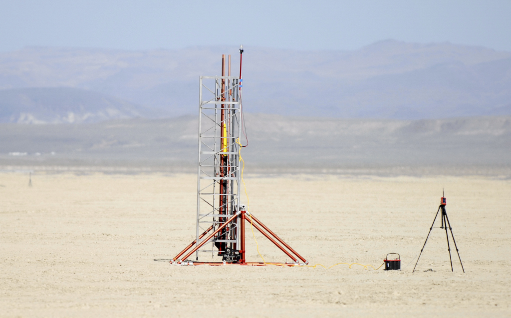
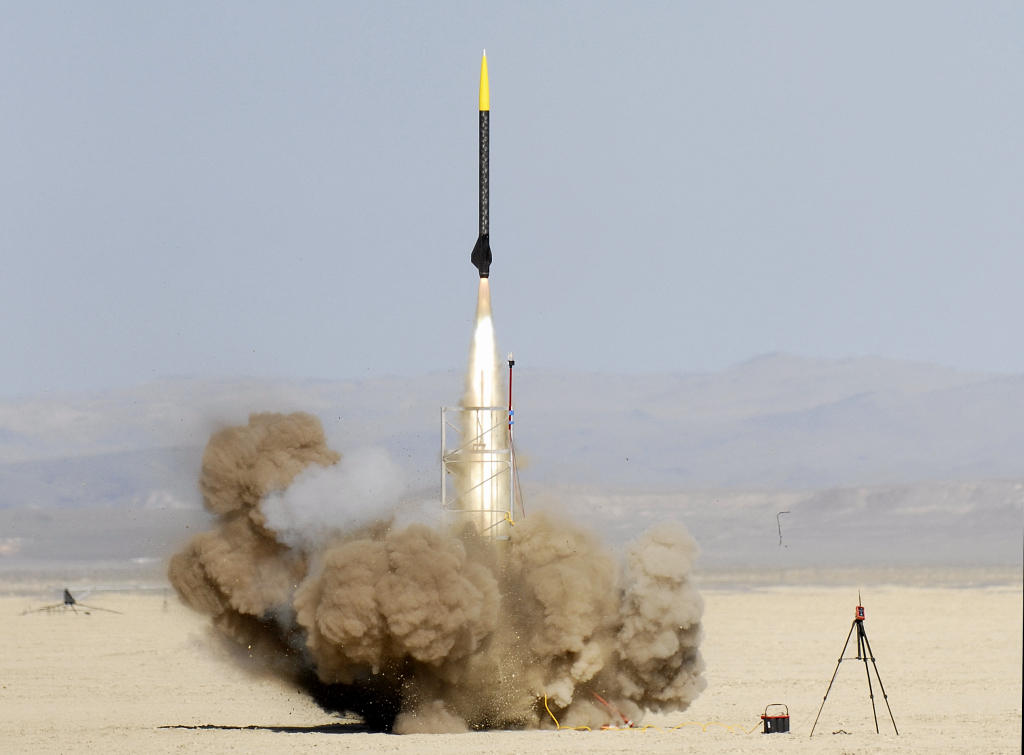
(Launch photos complements of Mark Canepa)
Anyhow, it was a great launch and we will try again next year.
Flight Testing – Tripoli Central California 02/21/2015
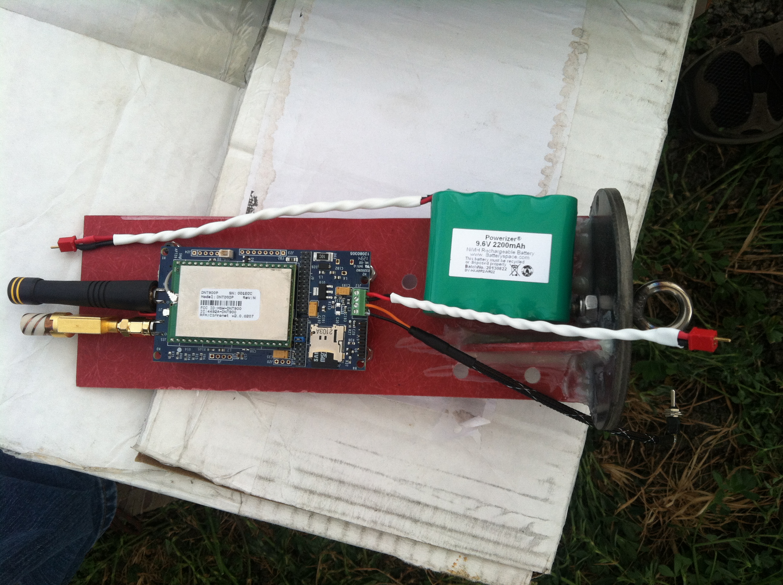
New season started! To start the year, Jimmy Franco flew his Dominator 4 on a Cesaroni L1355 Smoky Sam motor. Avionics sled installation picture and youtube video below.
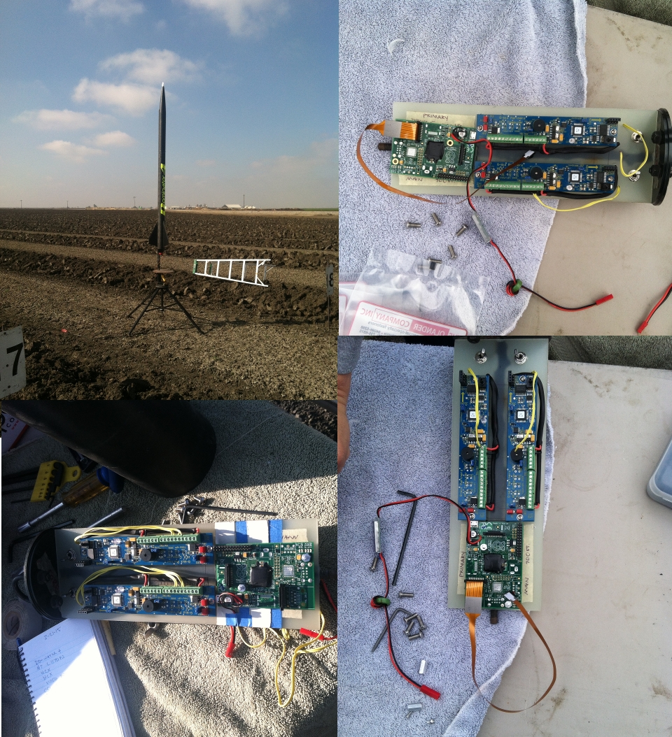
Revision 1 – Postmortem
- Good
- Everything works
- Very Low power (720p30 can run for almost 12 hrs on a 2600 mAh battery)
- Very low cost and durable
- Linux users dream
- Bad
- Windows does not recognize more than one partition on SD-Cards
- Windows does not recognize EXT-2 Filesystem
- Audio is not supported
You may say “fuck windows” … well, I agree; however, not all of my customers, users, or friends are as savvy with Linux so we have to help them. Most importantly, they should be able to eject the USB disk, plug into a PC and watch movies. Generating a product which creates one phone call in support is already a losing proposition. So, the high-level plan would be to use the USB bus interface for storage, and (while we’re in there), we should add audio as well – possibly multiplexing of files into MP4 file format if it is not too much of a performance and/or battery issue (but alas I digress).
Revision 2: Plans
- Rework new boards as before – but don’t remove USB chip or connector
- Add USB Audio ($2 – $12) + Microphone ($2-$15)
- Add USB Flash Drive (Cruzer 16GB $8.99, Cruzer 32GB – $11.87)
- Format as MSDOS Drive so Windows is happy and write file here
- Change SD-Card to smaller (8GB version) to save cost
- Redesign partitions and boot disks to only run Linux off the SD-Card
- PiCamera and storage volume on MS-DOS USB Flash Drive
- All to overcome SD-Card limitations on Windows
- Support Frame-Sync (Start time only) – 4 Boards may be chained so that the durations are correct (optimally frame-synchronized)
- Retest power: 1080p30, Mono+Stereo Audio, 4HD (3840×2160 post-processed)
- Re-evaluate battery selection
Revision 2 Hardware
- Raspberry Pi Model B – $39.95
- Low-profile microSD card adapter for Raspberry Pi – $2.50
- Adafruit Spy Camera for Raspberry-Pi – $39.95
- Universal Battery Elimination Circuit (UBEC) – $4
- SanDisk Cruzer Fit CZ33 16GB USB 2.0 Low-Profile Flash Drive – $8.99 (18Mbps Video is
- SanDisk Cruzer Fit CZ33 32GB USB 2.0 Low-Profile Flash Drive- SDCZ33-032G-B35 $15.10 – preferred for recording large movies at high quality)
- USB Microphone – from Amazon (ID 0d8c:013c C-Media) – $2.51
- Go with the cheaper and lower-cost 4GB SD-Card (since we’re not storing media on the SD-Card but the USB drive now instead)
USB Audio Capture
I originally started with the the Kinobo USB Microphone since it is a known element. When I received it and finally tested it, the quality was very good. The device shows up as below:
jfd@area51:$ dmesg
[19439.859646] usb 2-1.4: USB disconnect, device number 7
[19443.635953] usb 2-1.4: new full-speed USB device number 8 using ehci_hcd
[19443.742744] input: C-Media Electronics Inc. USB PnP Sound Device as /devices/pci0000:00/0000:00:1d.0/usb2/2-1/2-1.4/2-1.4:1.2/input/input19
[19443.743027] generic-usb 0003:0D8C:013C.0004: input,hidraw0: USB HID v1.00 Device [C-Media Electronics Inc. USB PnP Sound Device] on usb-0000:00:1d.0-1.4/input2
jfd@area51$ arecord -l
**** List of CAPTURE Hardware Devices ****
card 0: PCH [HDA Intel PCH], device 0: STAC92xx Analog [STAC92xx Analog]
 Subdevices: 1/1
 Subdevice #0: subdevice #0
card 1: Device [USB PnP Sound Device], device 0: USB Audio [USB Audio]
 Subdevices: 0/1
 Subdevice #0: subdevice #0
jfd@area51$
Recording & playback is as below:
jfd@area51$ arecord -f S16_LE -D hw:1,0 |aplayRecording WAVE 'stdin' : Signed 16 bit Little Endian, Rate 8000 Hz, Mono
Warning: rate is not accurate (requested = 8000Hz, got = 44100Hz)
 please, try the plug plugin
Playing WAVE 'stdin' : Signed 16 bit Little Endian, Rate 44100 Hz, Mono
Next step, making a WAV file from live capture on the Pi board. But first things first, that Kinobo dongle is $12 – wayyy to pricy. So we do some research and find that there is another one, only $2.60! Jackpot. So I got them both – when I tested them lsusb showed the both have the same C-Media chipset. The no-name version is here, cheap, very cheap! Link to Amazon. Note that according to Moores law, by end of 2015 this thing should be half the price – cheaper ones could be found on E-Bay, your mileage may vary but look for the C-Media chipset and you’re in good shape.
R2 Board Rework
 This time we remove the Audio and RCA connectors to save mounting space, along with the Ethernet plug. We just have two USB ports. I now have 4 reworked boards which have all the parts removed except the USB connector. I’ve decided we should go with the 4GB cards and get the Micro-SD taped down to prevent accidental ejection once the software is installed and finalized.
Whereas before we were simply going for lowest power, we found that the SD-Card was not a solution you could give to MSDOS/Windows users since they could not mount an EXTFS volume on a Windows system, and we wanted audio! So we decided to leave the USB as-is on the Model B board and connect the USB Thumbdrive so as to write out the movie onto it. While we’re at it, we picked up the USB audio device, so we’re no longer simply write H.264 elementary stream but a real movie.
R2 Recorder Software
The base OS version we installed is the latest Raspbian 2015-02-16 release. Link to the latest and greatest is here. Here’s how I install it on a Virgin 4-GB Micro-SD card (Sandisk 4GB from Adafruit or elsewhere:
#dd bs=4M if=2015-02-16-raspbian-wheezy.img | pv | dd of=/dev/mmcblk0
  7MB 0:00:01 [6.89MB/s] [<=>                                      ]
1.49GB 0:04:11 [ 330kB/s] [                                    <=> ]
781+1 records in2.55MB/s] [               <=>                      ]
781+1 records out
3276800000 bytes (3.3 GB) copied, 1184.99 s, 2.8 MB/s
3.05GB 0:19:45 [2.64MB/s] [             <=>                        ]
6400000+0 records in
6400000+0 records out
3276800000 bytes (3.3 GB) copied, 1185.05 s, 2.8 MB/s
#
Go get coffee or do something else for 15 minutes and wait. Put it in your system and check it boots. Configure as minimal system (magic).
Setting up the USB Drive
We don’t do anything to prepare it as it comes pre-formatted, insert it into the USB socket on the bottom slot of the Model B. We will also add the following line to /etc/fstab
/dev/sda1 /mnt vfat defaults 0 2
Raspivid
This wonderful program controls the camera and video encoder for generating compressed video bitstreams. We use H.264 and configure for the 1080p30 resolution at a high bitrate (since we have USB we might as well use it).
Our options for the Pi Camera are as follows.
Mode Size    Aspect Ratio  Frame rates      FOV       Binning
0 automatic selection
1 1920x1080 16:9           1-30fps          Partial   None
2 2592x1944 4:3            1-15fps          Full      None
3 2592x1944 4:3            0.1666-1fps      Full      None
4 1296x972  4:3            1-42fps          Full      2x2
5 1296x730  16:9           1-49fps          Full      2x2
6 640x480   4:3            42.1-60fps       Full      2x2 plus skip
7 640x480   4:3            60.1-90fps       Full      2x2 plus skip
So our plan will be to capture video from raspivid and use arecord to record the audio track. We will start the recordings at the same time so that we have synchronized media by design. Rather than wasting the battery power to mux and record in real-time, we do this offline after the flight. As an added bonus, we use a large bitrate to get great quality from the Camera.
#720p49
#!/bin/bash
raspivid -n -t 0 -w 1280 -h 720 -b 20000000 -fps 49 -o vi
deo.h264  | arecord -f S16_LE -D hw:1,0 -r 44100 file.wav &

#1080p30
raspivid -n -t 0 -w 1920 -h 1080 -b 20000000 -fps 30 -o vi
deo1080p.h264  | arecord -f S16_LE -D hw:1,0 -r 44100 file.wav &
LibAV & FAAC
What we’d really like to do, is use the system to capture/encode and multiplex both the audio video tracks (e.g. as MP4Box does only in real-time). We certainly can try to use avconv or FFMPEG to capture ALSA audio and multiplex the video stream to make an MP4 movie file.
Download, build and install the FAAC AAC Audio encoder as a prerequisite for AAC. Download, build and install the latest LibAV – we used version 11 “One Louder”.
#wget https://libav.org/releases/libav-11.3.tar.gz
#wget http://downloads.sourceforge.net/faac/faac-1.28.tar.gz
#tar -zxvf faac-1.28.tar.gz && make
#sudo make install
If you don’t want to build it yourself, for AAC you can also edit /etc/apt/source.list and add the lines for the non-free packages:
#deb http://www.deb-multimedia.org/ wheezy main non-free
#sudo apt-get install deb-multimedia-keyring
#sudo apt-get update
#sudo apt-get install libfaac-dev
Now build LibAV to get the avconv application
#tar -zxvf libav-11.3.tar.gz
#./configure --enable-nonfree --enable-libfaac
# make
# sudo make install
One can also install the avconv utility from the non-free repo (as above), using the command below:
# sudo apt-get install libav-tools
Now, we build our recording command. We tell the Bash shell to run raspivid, dump the H.264 stream to standard output, pipe that as input to avconv which will read audio data from the USB ALSA device, compress it into an AAC audio track, and then multiplex the audio & video into an MP4 file format output (onto the USB drive of course).
# raspivid -t 0 -fps 49 -w 1280 -h 720 -o - | avconv -i \
  pipe: -f alsa -ac 1 -i hw:0,1 -vcodec copy -acodec aac \
  -strict experimental test.mp4
FFMPEG
We can also install FFMPEG and do the same thing. Excellent instructions for building are at this site, note that we found the proper configure command for FFMPEG includes disabling the NEON instruction set (which is not available or required on R-Pi since it has a VPU); we also need to install libasound2-dev for the ALSA support (capture driver).
#Enable ALSA device capture
sudo apt-get install libasound2-dev

./configure --disable-neon --arch=armel --target-os=linux \
--enable-gpl --enable-libx264 --enable-nonfree \
--enable-libaacplus --enable-librtmp --enable-libmp3lame
The command to record then becomes
raspivid -n -t 0 -w 1280 -h 720 -b 1000000 -fps 30 -o - |
ffmpeg -strict -2 -y -ac 1 -f alsa -ar 44100 -i plughw:1 \
-r 30 -i pipe:0  -filter:a aresample=async=1 -c:a libaacplus \
-ab 24k -c:v copy video.mp4
See Raspivid and FFMPEG documentation for more details on what this command does. In testing however, we found that to make practical use of the recordings, we would need to bound the output to 1, 2 or 3 hours. This seems impracticable considering that we would run out of battery simply to perform a task simply done on the host PC (muxing the Audio/Video streams together to make an MP4 file). One other issue is that the 2835 platform cannot run in realtime for a Mono 44100Khz LPCM capture and H.274 720p30 while using USB for Microphone and storage media (32GB card). Some attempts at overclocking reach 13-20 FPS however, that usually ended up in the camera locking up and the CPU would get very warm (for 49fps, it is difficult to capture) so if you use Overclocking, only use it with the first (and most moderate) or medium setting.
In the end, our findings are that using raw capture of LPCM and Audio ES are the most reliable and simple strategy, uses the least amount of battery power (and therefore also generates the least amount), and most importantly ensures you are not dropping video frames, losing audio samples, overheating and losing precious run-time on your battery. Finally if either the audio or the video system fails, you are fault tolerant and may still record either audio or video!
Anyhow, this is one great area for future development – usage of the Pi-2 also comes to mind, and higher performance Micro-SD media may be an excellent alternative to USB in which case we can shrink the vertical form-factor like the simplified original V1 design.
Mastering Videos
So now we’ve flown and captured audio.wav and video.h264 – besides installing VideoLAN client (VLC), and/or unless you do ES video coding, you may have a hard time playing either the movie or audio file. To do this, you need to make what is known as a “system” or “muxed” stream. This is where you use a container format to interleave and format audio/video packets such that they are synchronized (and also carry other valuable information as you would find in an iTunes Audio (AAC/M4A) audio file – like track, date, and possibly GPS data). Anyhow, to do this in the most simple and portable (cross-platform) fashion, you can simply combine your audio (audio.wav) and video (video.h264) into an MP4 file as a movie. Unfortunately, MP4 does not recognize uncompressed (WAV) files so we first encode the audio track to MP3 using the LAME MP3 encoder or optimally, using the FAAC encoder for AAC format (as MP4 is designed for) before making an output movie file. The whole process is the two commands below:
# lame audio.wav audio.mp3
# MP4Box -add audio.mp3#audio -add video.h264 movie.mp4

or with AAC audio
# faac audio.wav
# MP4Box -add audio.aac#audio -add video.h264 movie_aac.mp4
If you encounter errors during the import process (e.g. you didn’t shut down cleanly, or you crashed) and presumably some of the file is corrupted, only import N seconds of data with the “dur” option; the syntax is below:
#MP4Box -add audio.mp3#audio:dur=360 -add video.h264#video:dur=360 \
/media/BC2A-7469/Nike-L3150.mp4
Overclocking – Tuning/Tweaking
There is an excellent page on tuning here, for standard Pi Builds or a Pi Build system, the only option we tried is the Turbo overclocking since this did not require a heat-sink and for compiles it works great. For high bitrate video and encoding, we wanted a little additional margin so we tried this, but the camera would often lock up with raspivid (see above). We also have the 2835 potted (without heat-sinks) to optimize power so we were very conservative. Using a Pi-2 and heat-sinks may be something for the future. Usage in a hot (nominally 150F) avionics bay may be problematic in some designs.
Backing up your SD-Card
Now that you have a master image, use the instructions here to backup your SD-Card and/or clone new ones.
sudo dd if=/dev/mmcblk0 bs=4MB of=raspbian-032115.img
Restoring your SD-Card
sudo dd if=raspbian-032115.img bs=4M of=/dev/mmcblk0
Setting up for Flight
As before, we will leave customization of the script in the root directory of the USB drive and add the script to be executed at start-up in rc.local. We add these scripts into the root directory of the USB Storage device (Sandisk 16/32GB)
# record.sh
#!/bin/bash
raspivid -n -t 0 -w 1920 -h 1080 \
-b 15000000 -fps 30 -o video.h264  | arecord -f S16_LE \
-D hw:1,0 -r 44100 audio.wav &
Add the following line to the end of /etc/rc.local
cd /mnt && ./record.sh &
Ok, we’re ready! Your system will now boot and record the audio/video files onto the USB driver. Once they are removed and copied to a Linux machine, you can use MP4Box or FFMPEG to mux the file offline as before.
R2 Flight Testing
The flight setup and configuration went well, except somehow we accidentally unplugged the camera after we got the avionics bay ready for flight! We did however get perfect GPS-1 Telemetry data and a great audio recording of the launch. Here’s the shocking horror when we opened the Av-Bay and found the camera cable was disconnected! We plan to fix this by using a cloth tape which will stick to the back of the camera cable and the actual PCB of the RaspberryPi; we also recognize the need to extend the Spy camera an additional length of FFC cable to accommodate longer runs of the camera to the Pi.
We will have to retest at the next launch. The good news is that we did at least capture the audio, see this mp3 file. The entire duration of the audio capture is 3hrs and 3 seconds. The initial battery charge voltage was 8.13 Volts, when recovered it measured 7.3 Volts.
Editing/Extracting Audio from Recording Files
First, listen to the movie file and correlate it with the video. First find the start point in VLC where lift-off is detected. Find the landing point: 1:15:37, now subtract the two: 1:15:37 – 1:12:04 = 3:33, convert to seconds we have 213 seconds. Now we exract the relevant audio from the file using the -ss and -t options.
# ffmpeg -y -ss 1:12:04 -t 213 -i audio.wav flight.wav
# ffmpeg -y -i flight.wav flight.aac
or
# faac flight.wav
Now, we make an MP3 file from the audio track:
# lame audio.wav audio.mp3
Note that on Ubuntu (Host/Dev PC), we can also make an AAC file from the audio track if we install the FAAC package for Free AAC:
 # sudo apt-get install faac
 # faac audio.wav
Spring Update – May 2015
We now have significant testing and validation of the system image and HW setup. To accommodate longer runs of the FFC cable, we’ve made an adapter of sorts – it’s the Top/Bottom sided 15 pin FFC connector soldered back to back (parts listed below). This is a 1mm pitch connector so while it can be done with a naked eye, we recommend a microscope when soldering for best results.
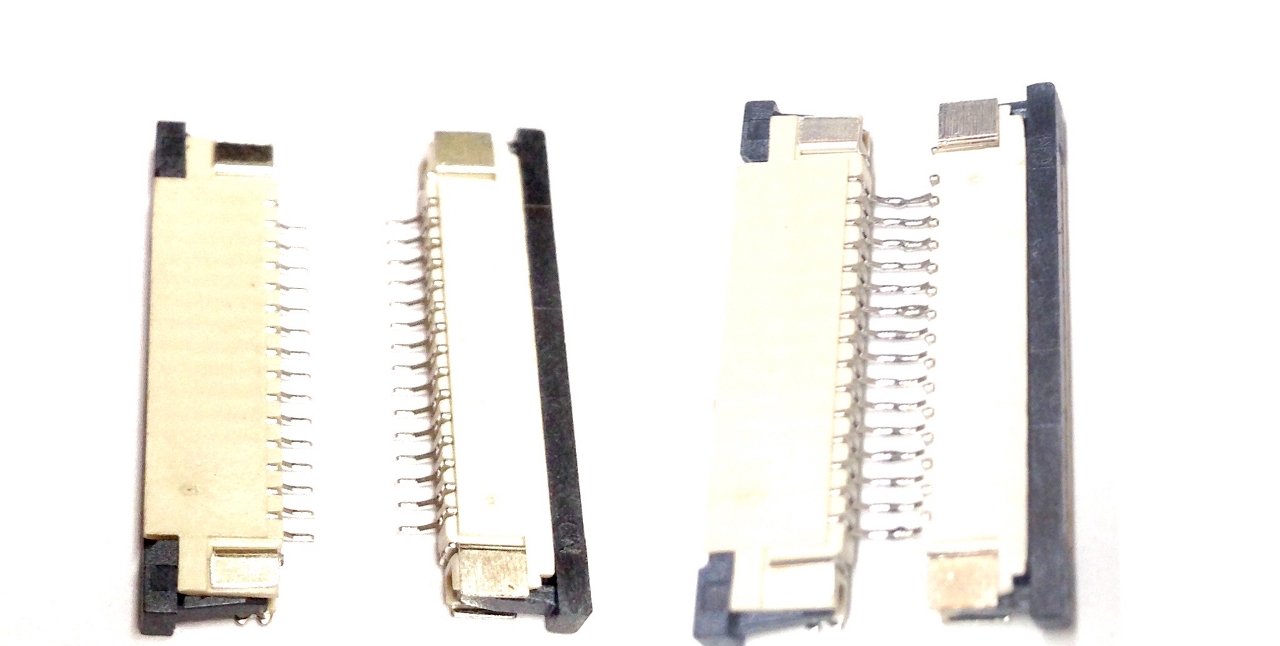
To make the connector more durable, it may be potted with cotronics. However, good results are found with marine epoxy putty.
Summer Update – June 2015
 We’ve since moved to the default recording script:
#!/bin/bash
 raspivid -n -t 0 -w 1920 -h 1080 -b 15000000 -fps 30 -o video.h264\
 | arecord -f S16_LE -D hw:1,0 -r 44100 audio.wav &
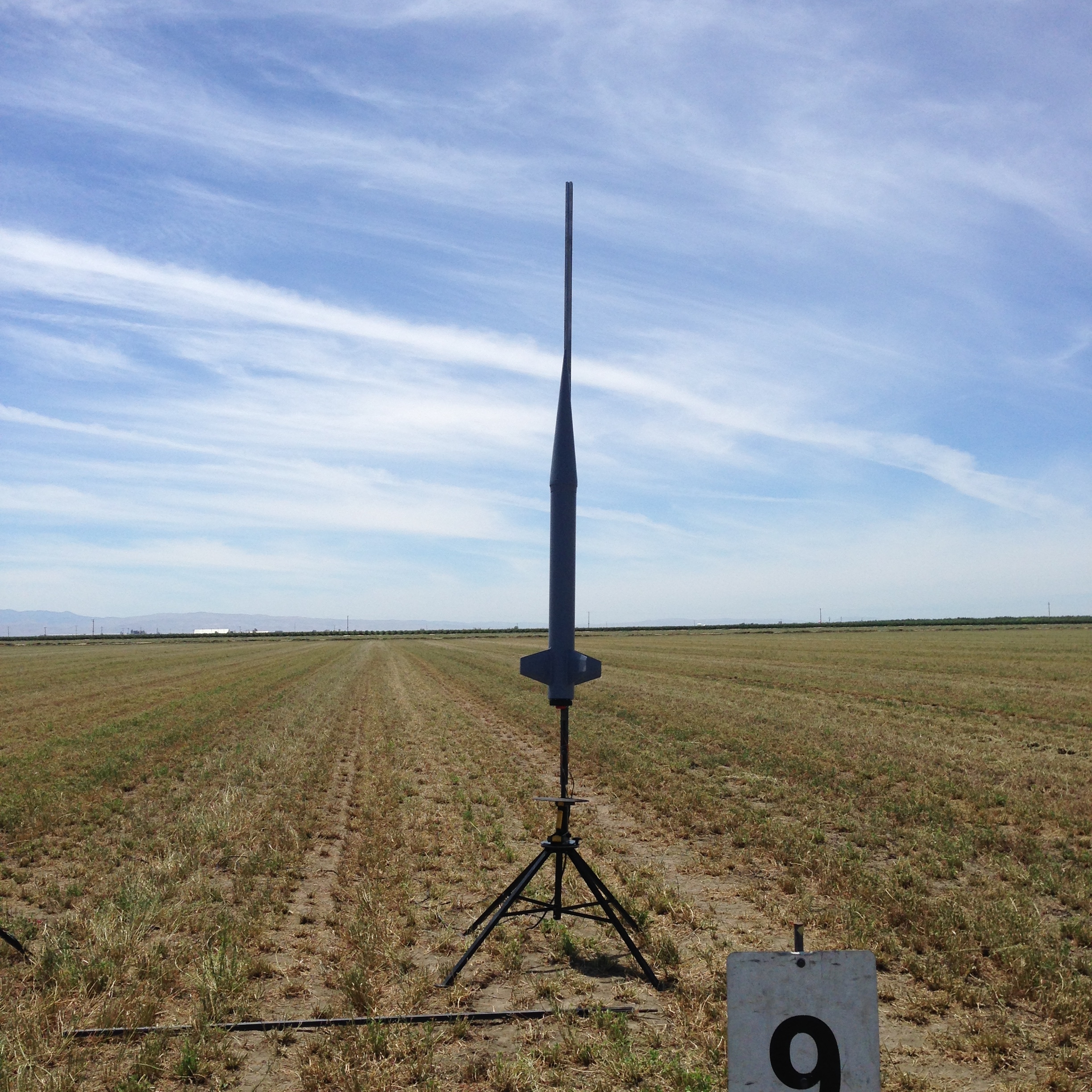
Jimmy Franco tested his Dominator-4 with an L850. This rocket useds the newly built extension cable to get over AV-Bay constraints. James Dougherty tested his 1/3 Scale Nike smoke with an L3150 motor; this rocket had GPS telemetry and GPS-1 system timing synched to the video track. Both flights worked and the post-processing results are as below.
Muxing and Non-linear H.264/WAV Editing with Open source tools
Here are the post-processing steps and how to verify the output result. First, we encode all the WAV files to MP3/AAC. Then, we use 30 FPS import settings for the video to match the framerate we used when the recording started from record.sh:
# lame audio.wav
# faac audio.wav
# MP4Box -fps 30 -add audio.aac -add video.h264#video Nike-L3150.mp4

AAC import - sample rate 44100 - MPEG-2 audio - 1 channel
AVC-H264 import - frame size 1920 x 1080 at 30.000 FPS
AVC Import results: 91497 samples - Slices: 1525 I 89972 P 0 B - 0 SEI - 1525 IDR
Now review timing of assets:
- 39:51/39:52 is Video of lift-off in MP4 file
- 30:45 is lift-off in audio file (audio.wav)
- 30:49 is lift-off in audio file (audio.mp3)29:36 is lift-off in audio file (audio.aac)
You analyze your video and they are not mixed correctly (video starts later than audio), The process we will use is to clip and remove the unwanted video from the start of the MP4 file, then use MP4Box to extract the resulting H.264 ES section, then remake the audio track from the original WAV file and remultiplex the file as a new MP4. First we extract 300 seconds
ffmpeg -i Nike-L3150.mp4 -ss 00:39:50 -acodec copy --vcodec copy -t 300 outputclip.mp4
Which copies 5 minutes from the starting point of 39:50. To look at the stream info using MP4Box, you do:
# MP4Box -info outputclip.mp4
* Movie Info *
 Timescale 1000 - Duration 00:05:00.002
 Fragmented File no - 2 track(s)
 File Brand isom - version 512
 Created: GMT Sun Jun 21 07:09:46 2015
File has root IOD (9 bytes)
Scene PL 0xff - Graphics PL 0xff - OD PL 0xff
Visual PL: Not part of MPEG-4 Visual profiles (0xfe)
Audio PL: Not part of MPEG-4 audio profiles (0xfe)
No streams included in root OD
iTunes Info:
 Encoder Software: Lavf53.21.1
Track # 1 Info - TrackID 1 - TimeScale 25000 - Duration 00:04:59.600
Media Info: Language "Undetermined" - Type "vide:avc1" - 7490 samples
Visual Track layout: x=0 y=0 width=1920 height=1080
MPEG-4 Config: Visual Stream - ObjectTypeIndication 0x21
AVC/H264 Video - Visual Size 1920 x 1080
 AVC Info: 1 SPS - 1 PPS - Profile High @ Level 4
 NAL Unit length bits: 32
Self-synchronized
Track # 2 Info - TrackID 2 - TimeScale 44100 - Duration 00:05:00.001
Media Info: Language "Undetermined" - Type "soun:mp4a" - 12920 samples
MPEG-4 Config: Audio Stream - ObjectTypeIndication 0x40
MPEG-4 Audio MPEG-4 Audio AAC LC - 1 Channel(s) - SampleRate 44100
Synchronized on stream 1
Alternate Group ID 1
#
Now, let’s extract the clipped H.264 ES video we just made to remultiplex with audio (shortened start end clipped at the end)
# MP4Box -raw 1 outputclip.mp4
Extracting MPEG-4 AVC-H264 stream to h264
# ls -lh outputclip_track1.h264
-rw-rw-r-- 1 jfd jfd 423M Jun 21 10:50 outputclip_track1.h264
#
Now let’s re-encode our audio track to match the timeline of the video, here its easier just to clip the WAV file and re-encode to a new AAC file. Now we know 30:45 is launch in audio file (audio.wav) from watching the video in VLC and we want 5 minutes of content, so we use:
# ffmpeg -i /media/BC2A-7469/audio.wav -t 300 -ss 00:30:45 \
  -acodec copy outputclip.wav
Now, let’s re-encode the new Audio clip to AAC format:
# faac outputclip.wav
Now, finally let’s remux our audio/video into an MP4 file:
# MP4Box -fps 25 -add outputclip.aac \
 -add outputclip_track1.h264#video Nike-L3150-short.mp4
Now we play this movie one final time in VLC and then clip the end (it’s on the ground at 4:38 (278 seconds) and all the altimeters have finished their status report). So we would do:
# ffmpeg -t 278 -i Nike-L3150-short.mp4 -ss 00:00:00 -acodec copy \
 -vcodec copy Nike-L3150-flight-and-landing.mp4
The resulting file may be uploaded to YouTube for the complete flight; the resulting file is as uploaded to YouTube as below:
Findings and Next Steps
The system works as expected, best of all we have beautiful footage, it can survive a prolonged high temperature environment to to over 150F (62.5C) and we can make future improvements. We also verified that the system will sustain over 26g’s for small bursts of time (< 1.44 seconds) and no harmful video degradation. First and foremost is the frame dropping issue which we plan to resolve with the below updated record script:
#!/bin/bash
echo 3 >/proc/sys/vm/dirty_background_ratio
echo 50 >/proc/sys/vm/dirty_ratio
echo 300 >/proc/sys/vm/dirty_writeback_centisecs
echo 300 >/proc/sys/vm/dirty_expire_centisecs
 raspivid --intra 4 -n -t 0 -w 1920 -h 1080 -b 15000000 -fps 30 -o video.h264 \ | arecord -f S16_LE -D hw:1,0 -r 44100 audio.wav &
Nike Findings
During the analysis of the Nike L3150 flight, we found that the audio and video was out of synch. The command used for recording during flight was:
#!/bin/bsdh

raspivid -n -t 0 -w 1920 -h 1080 -b 15000000 -fps 30 -o video.h264 |\
arecord -f S16_LE -D hw:1,0 -r 44100 audio.wav &
This produced :
#ls -l
-rw-r--r-- 1 jfd jfd  425471332 Mar 21 10:24 audio.wav
-rw-r--r-- 1 jfd jfd 4294967295 Mar 21 09:52 video.h264
#file audio.wav
audio.wav: RIFF (little-endian) data, WAVE audio, Microsoft PCM, 16 bit, mono 44100 Hz
# sox audio.wav audio.raw
So this should be 44100 *1 * 2 (rate * n_channels * bytes/channel) or 88200 bytes/seconds. The wave file is 425471332 bytes so if we subtract 44 bytes from the WAV file to remove the RIFF header, we have 425471288 bytes so that would be 425471288/88200 = 4823.93 seconds or 80.39 minutes = 1:20:39 of audio. So we should have roughly the same amount of video frames in duration. Since we recorded in 1080p30, we would expect to have 30*4823.93 or ~ 144717 frames.
The ffmpeg package can tell us how many video frames are in the file:
# ffmpeg -i video.h264 -vcodec copy -f rawvideo -y /dev/null 2>&1
The last line of output from the above command is the number of frames:
frame=91497 fps=410 q=-1.0 Lsize=0kB time=10000000000.00 bitrate=0.0kbits/s
Wow! That would be 91497/30 or 3049 seconds (right over 50 minutes). Assuming only 25p was selected for the encoding, we would have 3659 frames and that is still only 60 minutes – We’re missingover 20 minutes of video! The resulting images are of the highest quality so one would like to assume this is a bandwidth problem or some other issue with the encode, however, 15Mbps should only be 1.8 MB/sec so clearly we’re probably not IO limited via USB (most can do at least 4-5MB/sec of IO). The first thought may be to secede and chalk it up to a HW limitation and perhaps dropping the bitrate or looking at raw USB writing would be desirable. But the entire goal was to use an MS-DOS USB drive that we could use on a Windows PC!
Some research on the Pi Forum suggests that the best options are:
"-fps 25 -b 15000000"
And others have indicated the problem lies in the buffering done by the kernel and these parameters should be added to the start-up scripts on the Pi system:
    echo 3 >/proc/sys/vm/dirty_background_ratio
    echo 50 >/proc/sys/vm/dirty_ratio
    echo 300 >/proc/sys/vm/dirty_writeback_centisecs
    echo 300 >/proc/sys/vm/dirty_expire_centisecs
From the post below:
https://www.raspberrypi.org/forums/viewtopic.php?f=43&t=52556&start=75
You can google what the values stand for, if you’re interested in technical detail. In short, it makes the kernel write out to the SDcard (or USB stick) in small pieces very often – you’ll see the led blink quite a lot. You can try and tune the values; the key is to keep
dirty_background_ratio small and far away from dirty_ratio.
You’ll still need a reasonably fast media – at least slightly faster than the stream you’re recording. I have 10MB/s SD card (FAT filesystem) and record FullHD at 30fps (about 5MB/s of data), and it works perfectly fine 😎
9/17/16 update: NOTE we found the reason the audio was out of synch is because it was not actually recording at the specified sample rate of 2-channel 44100 but mono and most all of the muxing tools do not handle this correctly, we fixed this using the CD option to the record script and avoid using USB drives to write data and use Micro-SD instead to minimize video frame dropping. See the updated arecord script line below.
Final Recording Script (09/17/16)
The truth of the situation is that to get true 1080p30 output you MUST overclock unless you would like to use very low bitrate recordings. Experiments were done over a wide variety of bitrate and GOP settings to come up with what was the best trade-off in quality with the lowest bitrate. Finally, we found that using an intra-refresh of 3 frames (every three frames we shoot an IDR) we could run up to 15Mbps by tuning the kernel write cache and using the Medium overclock speed setting! We decided to tone this down to 10Mbps to leave some margin and account for very high motion; as a result we went with 10Mbps as the final H.264 ES output rate with an Intra-refresh period of 3 frames. To achieve this, we must overclock; use the raspi-config program to select the CPU overclock settings for Medium (900Mhz) (glad we tested this and it is safe). Image a fresh SD-Card with the Raspbian 03-21-15 image and follow the steps below (overclock and copy the USB drive recording scripts).
# raspi-config
# select over-clocking option below
 Medium 900MHz ARM, 250MHz core, 450MHz SDRAM, 2 overvolt t
Save the overclock settings and retest everything still works. The final recording script becomes as below, copy this script to your USB disk:
#!/bin/bash
# Fixup kernel flushing
echo 3 >/proc/sys/vm/dirty_background_ratio
echo 50 >/proc/sys/vm/dirty_ratio
echo 300 >/proc/sys/vm/dirty_writeback_centisecs
echo 300 >/proc/sys/vm/dirty_expire_centisecs
# run video/audio capture
raspivid -n -t 0 -w 1920 -h 1080 -b 10000000 -g 3 -fps 30 \
  -o video.h264 | arecord -f cd -D plughw:1,0 -r 44100 /data/audio.wav &
Mounting Notes
The camera will sit flush with a 1/8″ surface, it’s best not to have it flush to avoid melting at high mach speeds. Use a 19/64″ drill bit to drill the hole (Spy Camera). Pot the entire camera using Momentive Clear RTV108 (or equivalent) (do not remove the protective sticker on the Pi camera). Let this cure overnight. Trim the excess using an X-Acto or Scalpel razor blade. Mask, paint – finally remove the protective sticker before flight.
Summer Update – 09/08/15
We flew at TCC ID2015 (4th of Juplaya) at Blackrock, we had a total failure of the flight recorder. No audio was recorded and the video camera cable was found disconnected! We then found out (and confirmed) this happened when we closed the Avionics bay and disconnected the cable as a result of the USB connector snagging the FFC/FPC cable!!! The horror! We also found that the GPIO pins could short out if there is a lot of centripetal force (e.g. the rocket is spinning). Since then we have found four key things to add to your checklist for installation build/use at all times:
- Tape down the FFC/FPC cable to the board with strong tape (we use Advanced Technology Supply P212 or 6561 fire-proof electrical tape).
- Either remove the GPIO pins completely, or cover in RTV and/or wrap with tape.
- Mount the USB upright, this way the cable will not crimp or become disconnected as you slide your avionics bay through the airframe (more pictures and details on this later)
- The LED on the spy camera is not easily viewable from within the airframe, using Light-pipes is not any easier since it will not mount with the SMT LED on the FFC/FPC ribbon cable. For this, It is sufficient to add a remote LED and update the recording scripts one more time.
This also explains the failures both Jimmy and James had on their flights with no recorded video. The fixes here we decide to do on future designs and move on to LED status update capability.
LED Update
With this feature, you will add one LED to the system with a wire and a remote “status” capability, once the pipe command executes all of the commands, we will turn on and see the RED LED. Later the script will be modified to turn on constant – if any only if – the video.h264 file increases in size between two second intervals. A cheap and easy way to get flight status through a static vent hole and remote LED!
To Wire the LED, the best reference is the Pi GPIO reference. Wiring the LED we will use GPIO7 and the Ground which is at the end of the Pi GPIO header. This is as below:
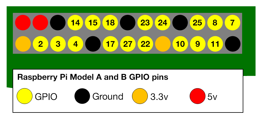
Since the max current on the pin is 16ma, and we’re 3.3v we have V=IR or 3.3 = .016R or R-3.3/.016 = 206 Ohm to drive it max output. Let’s limit to 300 Ohms.
You need a resistor in series with the LED to prevent burning it out. Choose one which limits the current to less than 16 mA (max current draw on a Pi GPIO pin), e.g. a 330 ohm will limit the current to 10 mA and it’ll still be bright. If the LED has two leads, one longer than the other,the longer lead is the positive (also known as the anode) lead.The resistor will attach to the negative (also known as cathode) (and shorter) side of the LED. The simple schematic is as below:
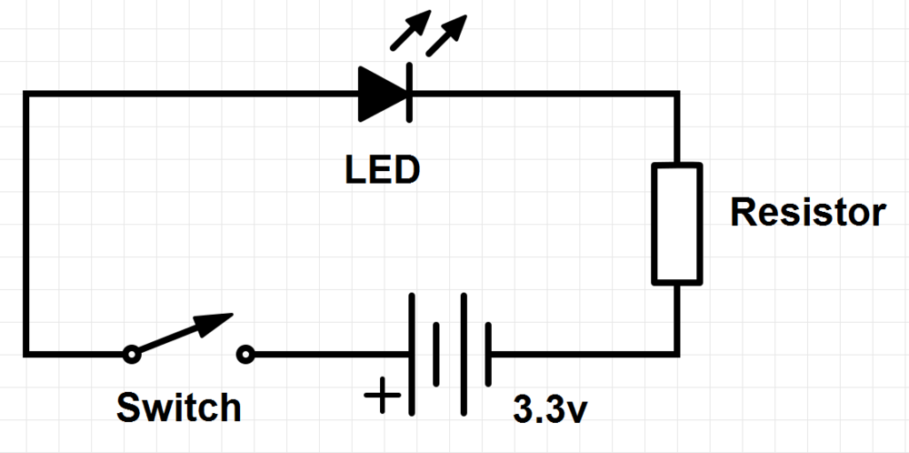
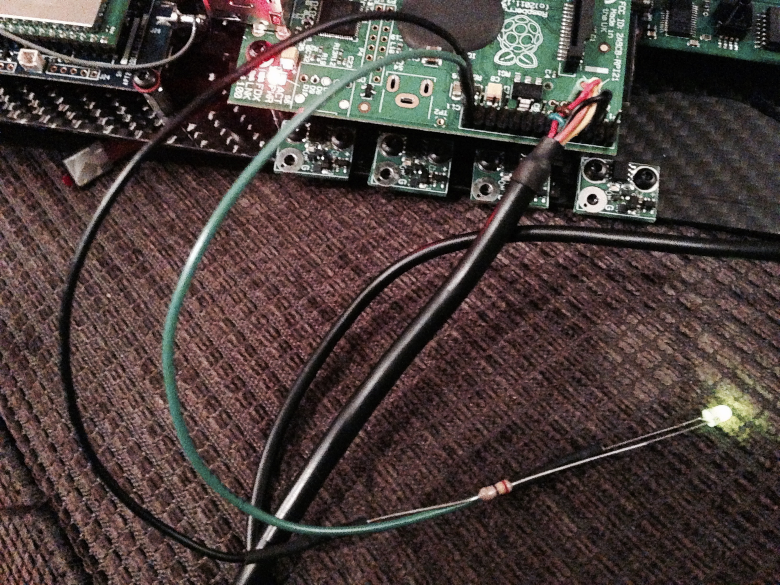
So now we build one of the above and connect it to GPIO7 and GND. We then use the sysfs command interface (with the goal of keeping it simple) to set GPIO7 as an output, and drive the value of the LED. Two sample scripts are as below:
Turn on LED on GPIO7
#!/bin/sh
echo 7 > /sys/class/gpio/export
echo out > /sys/class/gpio/gpio7/direction
echo 1 > /sys/class/gpio/gpio7/value
Turn off LED on GPIO7
#!/bin/sh
echo 7 > /sys/class/gpio/export
echo out > /sys/class/gpio/gpio7/direction
echo 0 > /sys/class/gpio/gpio7/value
NOTE: I used resistor values of 240, 390, and 470 Ohms. The green and red LEDs with 240 Ohms were the brightest (as expected). The power draw was negligible. You can use the above building blocks to customize your script as needed (monitor files, etc).
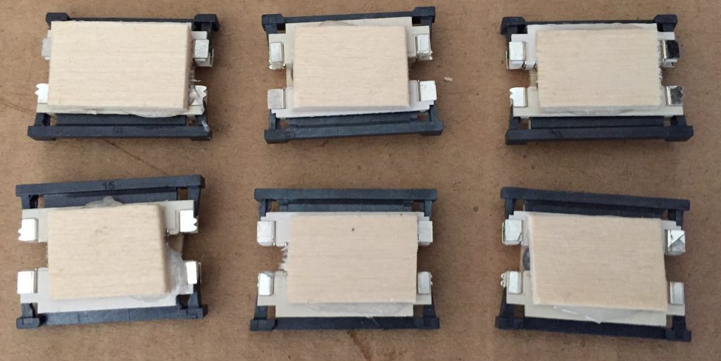
Spring (Pi-Zero) Update 2016
The Pi-Zero is out now, at $5 it justifies this entire effort. The adapter we made for the extension (Top/Bottom sided 15 pin FFC connector soldered back to back) is exactly what we need to adapt the spy camera! Here it is in all of it’s glory; we plan to mount 4 of these in our next rocket design for full 360 coverage.
Summer Update 2016
We plan to fly at the TCC Blackrock 2016 launch event our same Pegasus tested airframe (it does 45K consistently). This includes all the script, mounting, board/mechanical, and LED improvements. We also updated the Nike Smoke with the same improvements.
Blackrock Update 07/04/15
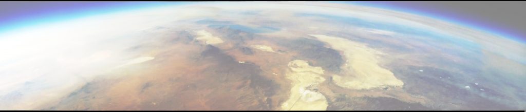
We flew the RocketPi in both the Nike smoke and the Pegasus high altitude sounding rockets. The Pegasus did 45K and got beautiful flight video and audio all the way up and down. We also were able to stitch a 170 degree view using PTGui for still frames from apogee.
 Notable are the changes we made for the Camera cable and GPIO pins – amazing what some tape and insulation can do!
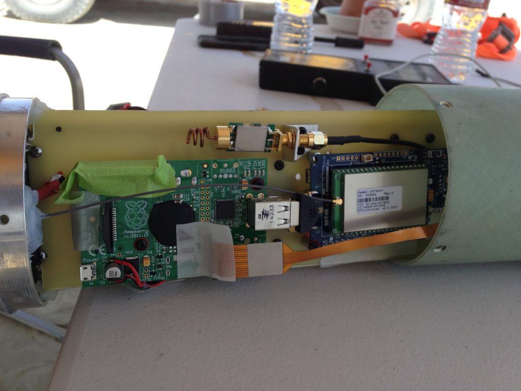
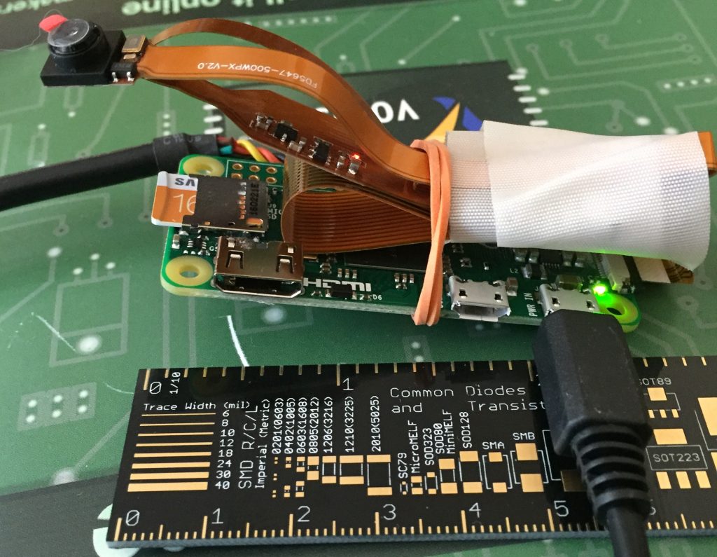
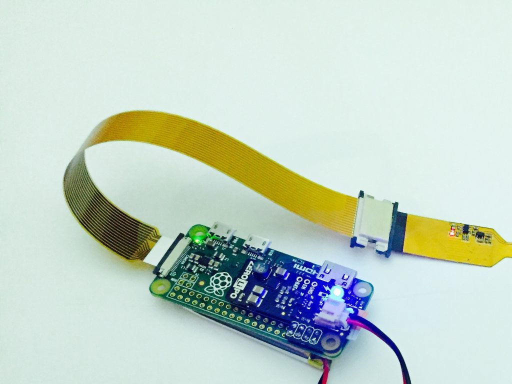
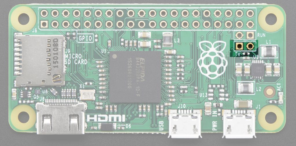
Pi-Zero Update – Raspberry Pi Zero Configuration
The folks at Raspberry Pi built the new v1.3 board with a camera input!
Now, we have everything we need in an even smaller package with all the
components we don’t need removed from the board – including the problematic
pin header (it could just cause shorts in most rocket applications). The Pi-Zero will be the third revision of the Video Data Recorder;the setup is amazingly simple; but first we need to setup a golden reference system to test images and tweak settings.
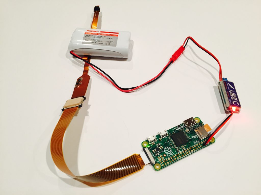
The only mods we’ll make for the dev system is to install the USB serial and use USB power as well as UBEC power; of course we use our special Camera connector as described above; I’ve recently build a 3D model for the cover fo the adapter, for the initial build, I simply used basswood and cut 10x15mm pieces and glued them to either side of the adapter to reinforce it while one connects the FPC cable. They weight 2 grams, send me email and SASE with postage for 2gm weight if you want one. If you’re a 3D Printer guru, send me email and I will send you the cad model and a unit with the connectors soldered.
USB Console
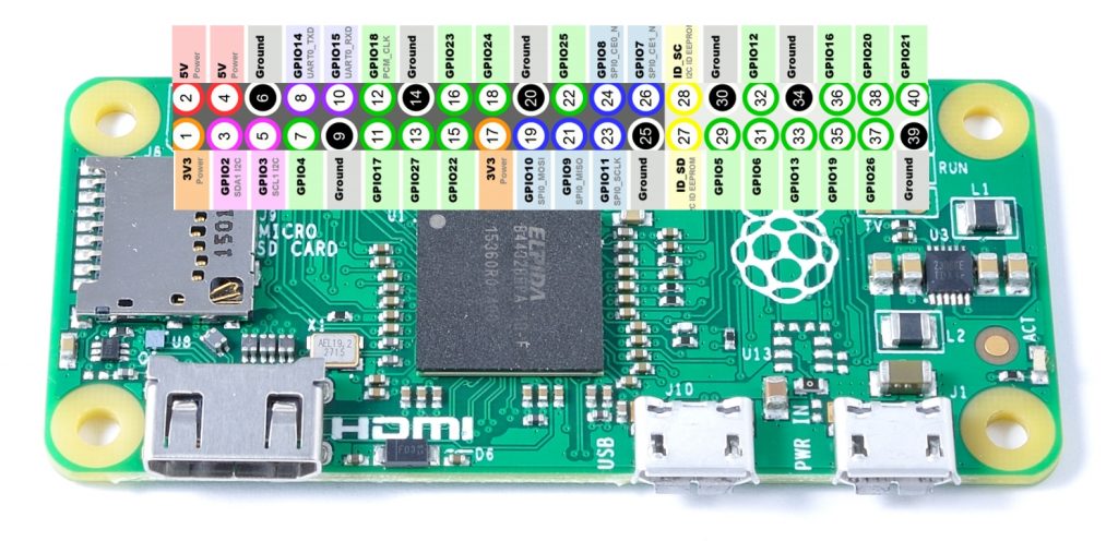
The Pi-Zero pinout is completely identical to the 2×20 headers on the Pi Model A+/B+/2B. It also has a composite video out/gnd pin and a run/gnd pin for reset. We will wire our serial port as before, and for power we will attach the UBEC to the first 5V and GND pins like below.
- Pin 4 – 5V from UBEC
- Pin 6 – Ground from UBEC
- Pin 8 (TXD) – UART RX
- Pin 10 (RXD) – UART TX
- Pin 14 (GND) – UART GND
Below is a good picture of the Pi-Zero GPIO Pin labeling.
TTL-232R-3V3 wiring below:
- TXD Orange (to Pi-Zero RXD – Pin 10)
- RXD Yellow (to Pi-Zero TXD – Pin 8)
- GND Black (to Pi-Zero GND – Pin 14)
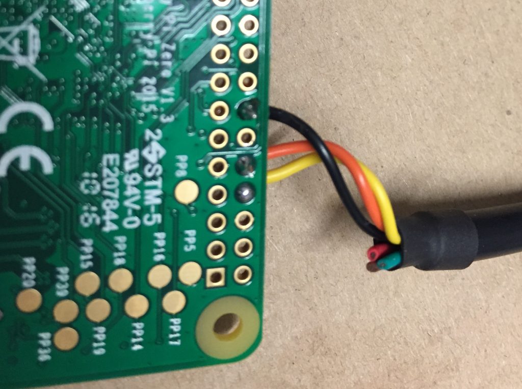
See also FTDI Cable datasheet.
Pi-Zero Software Setup
Install Debian Jessie – Raspbian Jessie (Full desktop image based on Debian Jessie)
Version: May 2016, Release date: 2016-05-27, Kernel version: 4.4 as outlined on RaspberryPi Website I am using 16GB Samsung Ultra SD-Cards ($7 on Amazon)
Initial Configuration
jfd@area51:~/rpi/cam1$ sudo minicom -D /dev/ttyUSB0
Default Jesse user/pass = pi/raspberry
pi@raspberrypi:~$ sudo passwd pi
Enter new UNIX password:
Retype new UNIX password:
passwd: password updated successfully
pi@raspberrypi:~$
Change it to pi/pi
sudo raspi-config
Select expand filesystem, reboot
sudo vi /etc/hostname
change to rocketpi
sudo vi /etc/hosts
add rocketpi to loopback interface
sudo raspi-config
Select enable camera, reboot and power-off; then attach camera with cable, carefully, then power-on.Since we’re not overclocking the Pi-Zero, we choose a smaller initial
bitrate, 8Mbps instead of the default 10Mbps
sudo mkdir /data
sudo vi /etc/rc.local
Here’s an example
#!/bin/sh -e
#
# rc.local
#
# This script is executed at the end of each multiuser runlevel.
# Make sure that the script will "exit 0" on success or any other
# value on error.
#
# In order to enable or disable this script just change the execution
# bits.
#
# By default this script does nothing.

# Print the IP address
_IP=$(hostname -I) || true
if [ "$_IP" ]; then
printf "My IP address is %s\n" "$_IP"
fi

printf "Starting Video recording [/data/video.h264]"
raspivid -n -t 0 -w 1920 -h 1080 -b 8000000 -fps 30 -o /data/video.h264&

exit 0
sudo reboot, see if it records
Debian GNU/Linux comes with ABSOLUTELY NO WARRANTY, to the extent
permitted by applicable law.
ls pi@rocketpi:~$ ls -l /data/video.h264
-rw-r--r-- 1 root root 79151104 May 27 12:07 /data/video.h264
pi@rocketpi:~$ ls -l /data/video.h264
-rw-r--r-- 1 root root 80269312 May 27 12:07 /data/video.h264
pi@rocketpi:~$ ls -l /data/video.h264
-rw-r--r-- 1 root root 81223680 May 27 12:07 /data/video.h264
pi@rocketpi:~$ ls -l /data/video.h264
-rw-r--r-- 1 root root 579473408 May 27 12:16 /data/video.h264
pi@rocketpi:~$
You will see the red LED on the Spy-Camera turn on as below.
Now, time to backup the card:
sudo dd bs=4MB if=/dev/mmcblk0 of=2016-05-27-raspbian-jessie-rocketpi.img
The resulting rocketpi image you can download here (gzipped). Now, to setup more systems, I used a 8MB block size and the copy operation was a little bit faster:
sudo dd if=2016-05-27-raspbian-jessie-rocketpi.img of=/dev/mmcblk0 bs=8M
Using Tenergy 7.4V Li-Ion 2200Ma batteries and a JST 2-Pin connectors,plug in and the system boots. The Red Camera LED will light up when recording starts.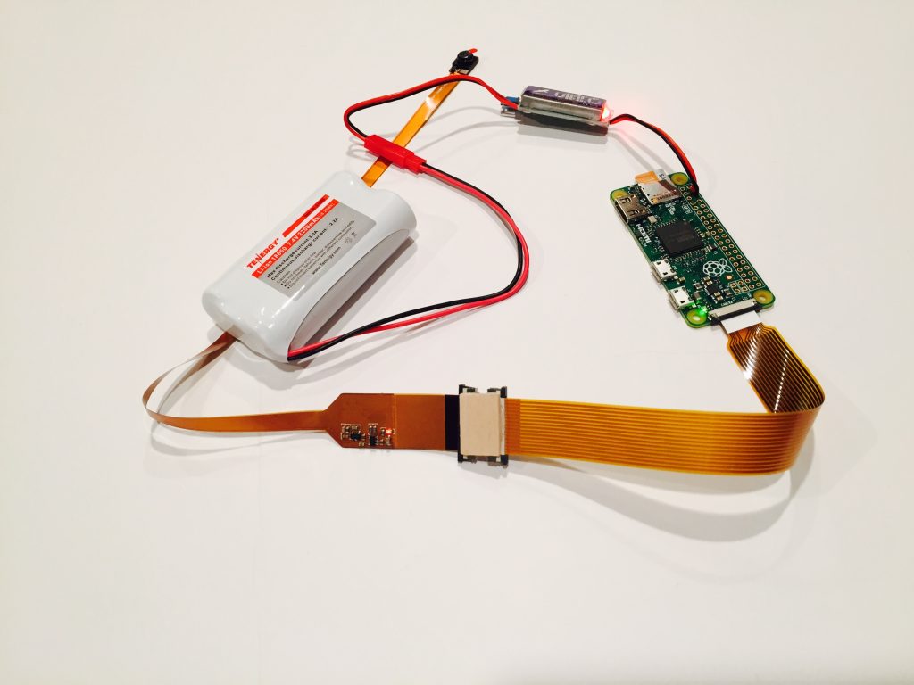
 Next, we will add audio recording to SD-Card with the Audio adapter board and by extending the command line in rc.local
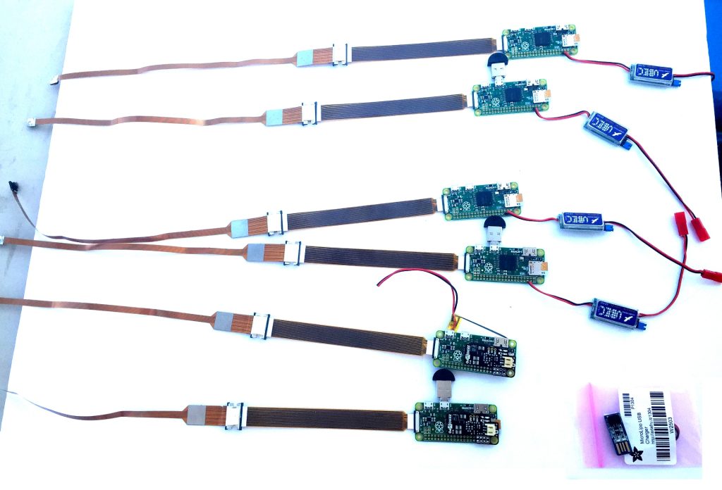
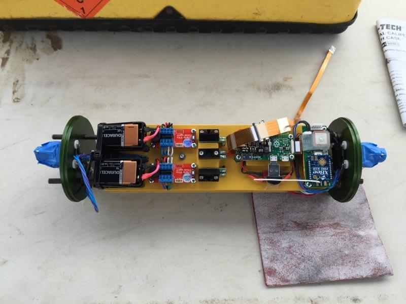
First Massive Pi-Zero Build
Here is the parts list and a picture of all the boards I built for folks at TCC for our test launch. Notice some of them have the new Pimoroni PiZero Lipo adapter which lets you run the entire system off of a 3.7v Lipo battery (UBEC Replacement). We added the PiZero Lipo to some of our systems (image contrast adjusted for clarity).
Pimoroni Pi-Zero Lipo Update
The folks at Pimoroni have introduce the Pi-Zero Lipo adapter; this unit solders on top of your Pi-Zero and has a boost circuit to allow your Pi-Zero to run off of a LiIon/Lipo battery. We’re using the 2000mAh variety as can be found here, this will give us about 1hr with audio. Further testing needs to be done with this configuration however, and it does not lend itself well to multi-camera systems where the UBEC can power two units from one battery. For a single-setup however, it’s the way to go, and if you want to save weight and are sure to fly right away, its the best setup there is! Pictured below is our setup with an 1800 mA battery which fits right under the Pi-Zero!
Adding Audio Support to Pi-Zero
We will adapt the C-Media USB Audio recording device to Micro-OTG form factor by using the Micro-OTG to USB Adapter on the parts-list below. Insert the card into the USB port on the system (not the battery port). Be careful inserting the OTG to USB Micro-Adapter into the USB Audio Device (the shielding is usually made from cheap tin and as the insertion force is quite large you may get metal splinters in your fingers as I did).
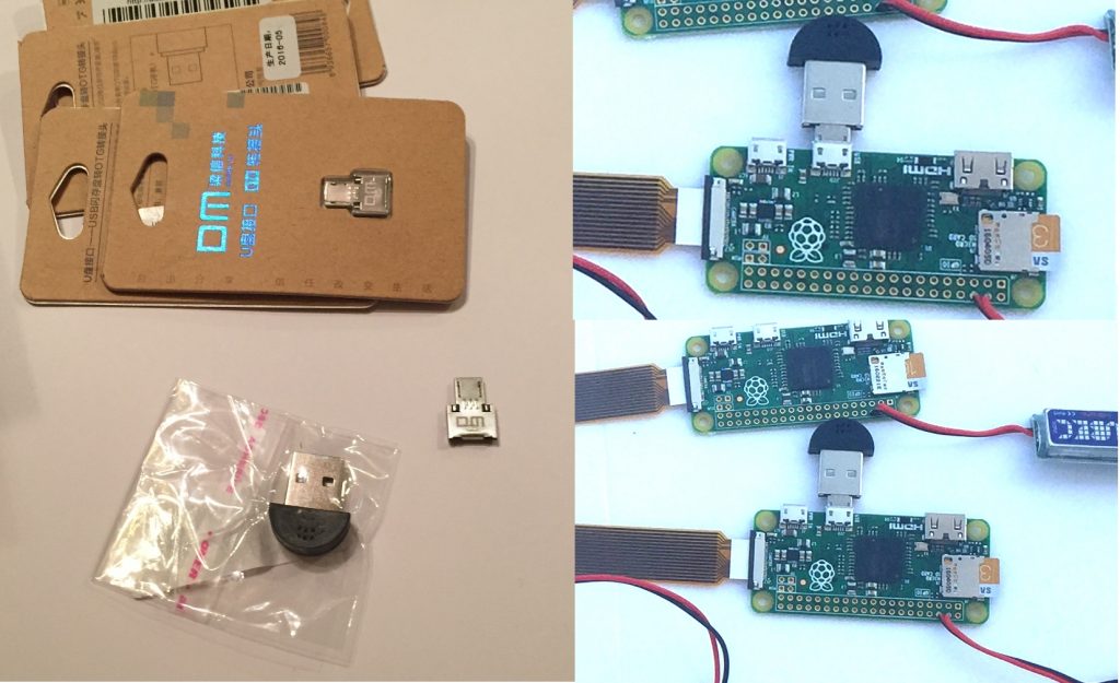
Now insert into your Pi-Zero, if it works, “dmesg” output show the below messages in your system log:
pi@rocketpi:~$ dmesg |tail -20
[   14.689076] Indeed it is in host mode hprt0 = 00021501
[   15.198645] usb 1-1: new full-speed USB device number 2 using dwc_otg
[   15.198873] Indeed it is in host mode hprt0 = 00021501
[   15.610343] usb 1-1: New USB device found, idVendor=0d8c, idProduct=013c
[   15.610376] usb 1-1: New USB device strings: Mfr=1, Product=2, SerialNumber=0
[   15.610391] usb 1-1: Product: USB PnP Sound Device
[   15.610406] usb 1-1: Manufacturer: C-Media Electronics Inc.
[   15.641450] input: C-Media Electronics Inc.       USB PnP Sound Device as /d0
[   15.699118] hid-generic 0003:0D8C:013C.0001: input,hidraw0: USB HID v1.00 De2
[   16.097074] usbcore: registered new interface driver snd-usb-audio
[   18.249105] random: nonblocking pool is initialized
[   37.641273] Bluetooth: Core ver 2.21
[   37.641604] NET: Registered protocol family 31
[   37.641625] Bluetooth: HCI device and connection manager initialized
[   37.641659] Bluetooth: HCI socket layer initialized
[   37.641681] Bluetooth: L2CAP socket layer initialized
[   37.641738] Bluetooth: SCO socket layer initialized
[   37.768931] Bluetooth: BNEP (Ethernet Emulation) ver 1.3
[   37.768985] Bluetooth: BNEP filters: protocol multicast
[   37.769032] Bluetooth: BNEP socket layer initialized
pi@rocketpi:~$
Now, add the below line to rc.local so that it is below your raspivid line
printf "Starting Audio recording [/data/audio.wav]"
arecord -f cd -D plughw:1,0 -r 44100 /data/audio.wav &
Here is my full output:
pi@rocketpi:/etc$ cat /etc/rc.local |tail -8

printf "Starting Video recording [/data/video.h264]"
raspivid -n -t 0 -w 1920 -h 1080 -b 8000000 -fps 30 -o /data/video.h264&

printf "Starting Audio recording [/data/audio.wav]"
arecord -f cd -D plughw:1,0 -r 44100 /data/audio.wav &

exit 0
For testing, boot the Pi, record some TV or whatever you want. The video.h264 and audio.wav files are created in the /data direcory and all of the post-processing techniques described to date still apply.
Pi-Zero Flight Testing
Jimmy Franco did the first flight test, Greg Morgan did the second flight test. Here is a picture of Greg Morgan’s AV-Bay and also the YouTube video onboard his Frenzy.
 Beautiful GPS-1 setup on the back-side for tracking during flight. Here is is in action….
nice job and Congrats Greg!
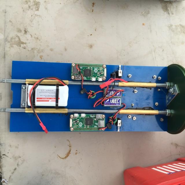
Quad Pi-Zero
Jimmy Franco built the first Quad-Pi for QHD Flight recording. Shown here below is the setup: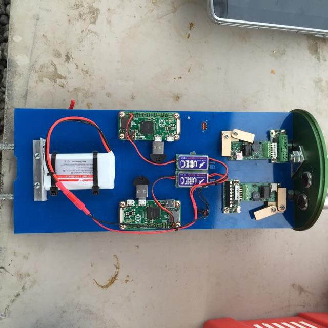
The Quad HD (2180p) video is available below:
Also, some stunning aerial panoramic views of the launch site and the flight-line below.
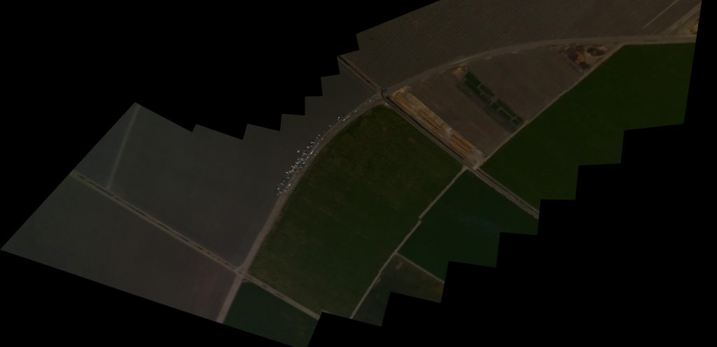
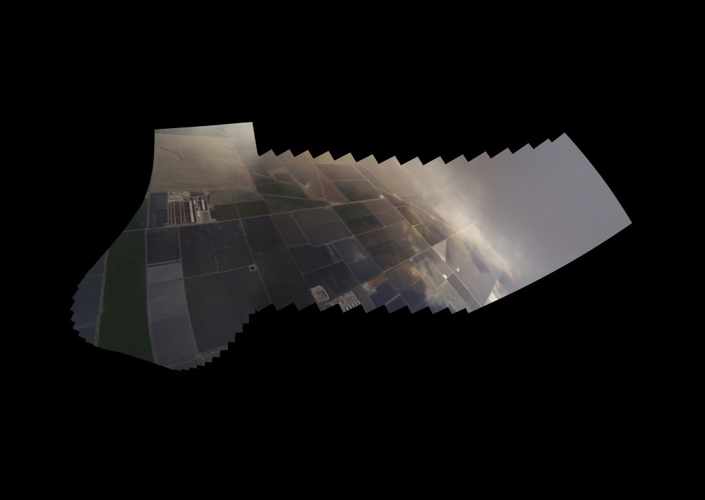
Our next plan is to align the cameras better and work on multi-camera synchronization to speed up editing.
11/16/16 – Pi-Zero Camera Update
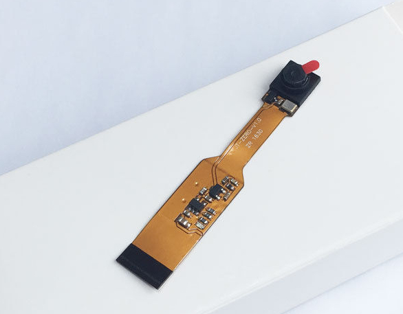
As expected, there is now a “Spy Camera” (very small) cam just for Pi-Zero!
This means shorter cable and no special adapter required for the Spy cam!
You can find tiny Zero Camera for $16.95 on Ebay which means no special cable is now required for the Tiny RocketPi Zero.
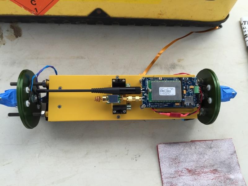
First Person View(er) (FPV) – Live Downstream Video Broadcast
UAV’s (Drones) have driven the cost down substantially on live video Broadcast Hardware; these systems use analog broadcast technology from yester-year and are driven by HDMI and/or TV (NTSC) input. Of course, we could do a live RTP stream over Wi-Fi but that would be limited at Range and it is still questionable how well even Analog
broadcast will work for Rockets. Nevertheless, these systems are available for very low cost and claim ranges of 6000m with a 2Watt setup and omni-directional (Cloverleaf) antenna setup (even greater distances are possible with antenna aiming circuitry – more on that later). Other systems and variants similar to the below may be found, but these were chosen for the best price/performance after experimentation with a few of them (contact me for more details).
This is a complete system – in includes a 2Watt Transmitter (33dBm) and an NTSC display and receiver along with the clover-leaf antenna pair. The system will ship quite fast
as USA Quadcopters have shipping in the USA, are reliable, and they provide the best value packages. The transmitter alone (and the pair of Cloverleaf antennas) can also be purchased separately. Finally, You can also just purchase the Transmitter ; make sure you’re ordering the 2 Watt version or higher, you will find a huge number of suppliers for the cloverleaf antenna (just remember the Boscam unit uses an RPSMA jack so your antenna will need an RPSMA plug (Female) connector.
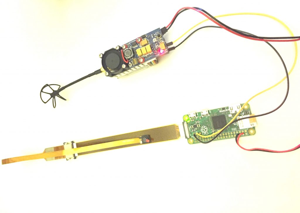
The Pi and in particular the Pi-Zero have a TV (NTSC/PAL) output which allows concurrent capture and rendering of live video. In fact, the TV/HTMI output has always been present we simply disabled it (to reduce power consumption) by starting raspivid with the -n switch. On the Pi-Zero the Composite signal and ground are shown below, we simply need to connect the TV Input to the Boscam Transmitter.
The Pin to the left, marked TV, is the signal (+) line and the pin to the right of it is the ground (-) line. The Boscam signalling is listed below.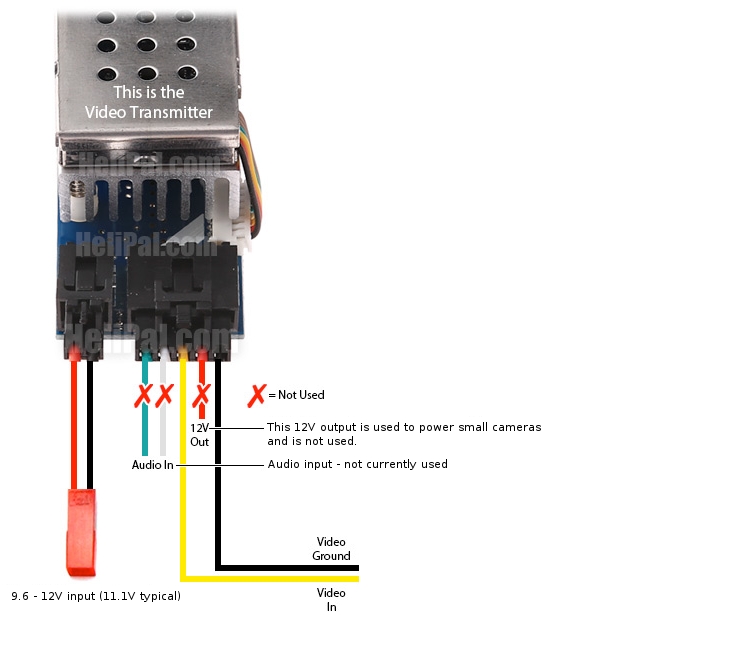
I’ve built the FPV setup by simply connecting as in the Boscam Wiring above for
TV-Out on Pi-Zero.A picture of the whole setup (running off of a 9.6v 2Ah battery is below).
The display driver will automatically force output to TV-Out and the system will run with no software modifications besides removal of the “-n” command line option. The startup command for video now becomes:
raspivid -f -t 0 -w 1920 -h 1080 -b 8000000 -fps 30 -o /data/video.h264&
You’ll also want to disable X support, once booted, issue
sudo raspi-config
 - enable overscan
 - enable shell login (disable X, console only)
You may notice the entire screen is not being used and there are either black borders vertically (pillar boxes) or horizontally (letter boxes). You can remove these by enabling overscan on the TV output port. With the hardware being tested above, I found to maximize overscan on the screen so you should edit boot/config.txt and uncomment these two lines:
overscan_top=16
overscan_bottom=16
You may also want to disable the Raspberry Pi Logo on boot, you can do this
by adding “logo.nologo” to /boot/cmdline.txt (I prepended it to the beginning). Note that this file is just one big long string.
Finally, the keyboard/display management for the framebuffer console (kbd) will still blank when there is no activity for 30 minutes (and there will not be since we do not
currently take input). So we need to disable framebuffer blanking; to do this edit the file below:
sudo nano /etc/kbd/config
Change these two lines.
# screen blanking timeout. monitor remains on, but the screen is cleared to
# range: 0-60 min (0==never) kernels I've looked at default to 10 minutes.
# (see linux/drivers/char/console.c)
BLANK_TIME=0 (Was 30)

# Powerdown time. The console will go to DPMS Off mode POWERDOWN_TIME
# minutes _after_ blanking. (POWERDOWN_TIME + BLANK_TIME after the last input)
POWERDOWN_TIME=0
Re start the file or just reboot
sudo /etc/init.d/kbd restart
And now you’re all set! You now have live capture and recording of 1080p and broadcasting SD-TV (720×480 NTSC) live to the ground-station.
September 2017 – PiZero in Action
Greg Morgan flew his CTI N1560 powered rocket Bottomz up at BALLS26 to 62,734′ MSL (59,448′ AGL) with GPS-1 on-board to attain a new TRA altitude record for single N class. See below the RocketPi Zero video flight recorder in action!
One thing we found was that at high-altitude, the Spy camera seemed to lose image quality; later inspection found that this may be due to the seal of the camera module itself as at altitude, this seal may burst causing lens aberration. Venting the camera to atmospheric pressure would be the next step for testing.
Stay tuned for more important updates and flight testing results.
Pi-Zero Parts list
- Raspberry Pi Zero v1.3
- Tiny OTG Adapter – USB Micro to USB
- Samsung Ultra-HD 16 or 32GB Micro-SD
- Hobbywing 5V 3A UBEC
- C-Media USB Microphone
- Tiny Zero Camera for $16.95 on Ebay
OR - Original Spy Camera and Adapter (described here)
- Tenergy 7.4v 2200mAh LiIon Pack
- Tenergy 7.4V 900mAh 25C LIPO Pack – Optional, use this one for shorter flights or space constrained vehicles.
- PiZero LiPo
- Micro Lipo Charger
- Switched JST PH Connector
- Li-Po Battery (2000mAh)
- LiPo battery (2000mAh)
- LiPo battery (1000mAh)
- 2 Watt FPV Broadcast System
Next Steps
- Continued Flight testing Pi-Zero throughout the Year, including Pi0 Lipo and camera tuning/testing
- 1080p audio/video recording and 4 HD
- Simplified Camera connection
- FPV 5.8Ghz Transmission via TV-Out
Downloads
- Final R2 Image (Raspbian 2015-03-15 based) – DD Image /4GB Sandisk Micro-SD
- Final R3 Image (Pi-Zero – Raspbian 2016-05-27 based) – DD Image/32G Micro-SD
- USB Scripts – copy to USB drive
Mods
- Using the GPIO pins on Raspberry Pi
- Altimeter using BMP085 Barometer and also this site for R-Pi
- Altimeter using MS5803 Barometer
- 10DOF IMU using Adafruit L3GD20H + LSM303 + BMP180
Future Directions
- FPV and Antenna Tracking
- GPS-1 expansion board (2017)
- Add Flight Altimeter with IMU board and external Pyro channels
- Fly again at BALLS this year (BALLS26)
- Bigger/badder flights with more altitude (the July 2015 flight was ~50K MSL)
- Multiple cameras at high resolution and frame-rate (just start them all with one master and slaves gated via a GPIO pin, power master up last)
- Programs/Scripts for OSD Overlays of GPS-1 telemetry and sensor data
Links
- VideoLAN Client
- Python
- Audio
- Microphones
- Camera and Video
- Supported Video Modes
- Details on Pi Camera module
- Live Broadcast Transmission with the UT-100 DVB-T Modulator
Credits
Special thanks to Gianluca Filippini (gianluca@autosburla.com) for the original idea, initial software and the motivation. Special thanks to Al Goncalves for the updated ideas on Spy-Camera (and actually having me take power measurements). Special thanks to Jimmy Franco for all of his support and flight testing and of course special thanks to Gordon Hollingworth for his awesome support and continuing strides towards excellence.
Contact
James F Dougherty <jfd@realflightsystems.com>
You must log in to post a comment.